About a month ago I talked about using R for plotting GPS coordinates. Recently I found out that the  Cessna 172 I fly in has had its G1000 avionics updated. Garmin has added the ability to store various flight data to a CSV file on an SD card every second. Aside from the obvious things such as date, time and GPS latitude/longitude/altitude it stores a ton of other variables. Here is a subset: indicated airspeed, vertical speed, outside air temperature, pitch attitude angle, roll attitude angle, lateral and vertical G forces, the NAV and COM frequencies tuned, wind direction and speed, fuel quantity (for each tank), fuel flow, volts and amps for the two buses, engine RPM, cylinder head temperature, and exhaust gas temperature. Neat, eh? I went for a short flight that was pretty boring as far as a number of these variables are concerned. Logs for cross-country flights will be much more interesting to examine.
With that said, I’m going to have fun with the 1-hour recording I have. If you don’t find plotting time series data interesting, you might want to stop reading now. :)
First of all, let’s take a look at the COM1 and COM2 radio settings.
> unique(data$COM1)
[1] 120.3
> unique(data$COM2)
[1] 134.55 120.30 121.60
Looks like I had 3 unique frequencies tuned into COM2 and only one for COM1. I always try to get the  ATIS on COM2 (134.55 at KARB), then I switch to the ground frequency (121.6 at KARB). This way, I know that COM2 both receives and transmits. Let’s see how long I’ve been on the ATIS frequency…
> summary(factor(data$COM2))
 120.3  121.6 134.55
     1   3303     70
It makes sense, between listening to the ATIS and tuning in the ground, I spend 70 seconds listening to 134.55. The tower frequency (120.3 at KARB) showed up for a second because I switched away from the ATIS only to realize that I didn’t tune in the ground yet. Graphing these values doesn’t make sense.
I didn’t use the NAV radios, so they stayed tuned to 114.3 and 109.6. Those are the Salem and Jackson VORs, respectively. (Whoever used the NAV radios last left these tuned in.)
To keep track of one’s altitude, one must set the  altimeter to what a nearby weather station says. The setting is in Inches of Mercury. The ATIS said that 30.38 was the setting to use. The altimeter was set to 30.31 when I got it. You can see that it took me a couple of seconds to turn the knob far enough. Again, graphing this variable is pointless. It would be more interesting during a longer flight where the barometric pressure changed a bit.
> summary(factor(data$BaroA))
30.31 30.32 30.36 30.38
  262     1     1  3110
Ok, ok… time to make some graphs… First up, let’s take a look at the outside air temperature (in °C).
> summary(data$OAT)
   Min. 1st Qu.  Median    Mean 3rd Qu.    Max.
    4.0     6.8    12.2    11.5    16.0    18.5
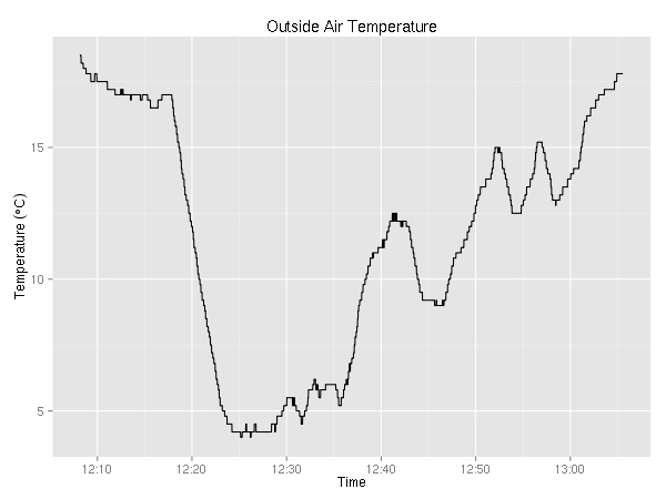
In case you didn’t know, the air temperature drops about 2°C every 1000 feet. Given that, you might be already guessing, after I took off, I climbed a couple of thousand feet.
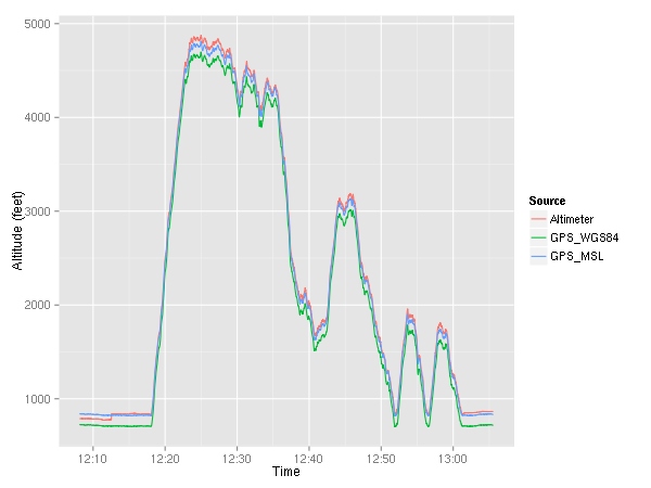
Here, I plotted both the altitude given by the GPS ( MSL as well as
  WGS84) and the altitude given by the altimeter. You can see that around 12:12, I set the altimeter which caused the indicated altitude to jump up a little bit. Let’s take a look at the difference between the them.
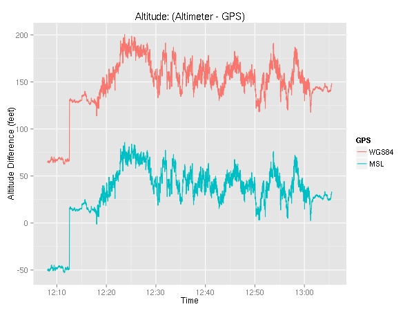
Again, we can see the altimeter setting changing with the sharp ~60 foot jump at about 12:12. The discrepancy between the indicated altitude and the actual (GPS) altitude may be alarming at first, but keep in mind that even though the altimeter may be off from where you truly are, the whole air traffic system plays the same game. In other words, every aircraft and every controller uses the altimeter-based altitudes so there is no confusion. In yet other words, if everyone is off by the same amount, no one gets hurt. :)
Ok! It’s time to look at all the various speeds. The G1000 reports indicated airspeed (IAS), true airspeed (TAS), and ground speed (GS).
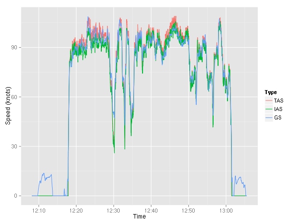
We can see the taxiing to and from the runway — ground speed around 10  kts. (Note to self, taxi slower.) The ground speed is either more or less than the airspeed depending on the wind speed.
Moving along, let’s examine the lateral and normal accelerations. The normal acceleration is seat pushing “up”, while the lateral acceleration is the side-to-side “sliding in the seat side to side” acceleration. (Note: I am not actually sure which way the G1000 considers negative lateral acceleration.)
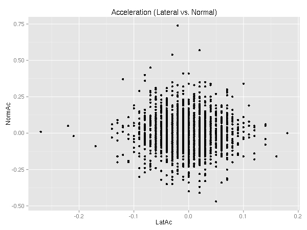
Ideally, there is no lateral acceleration. (See  coordinated flight.) I’m still learning. :)
As you can see, there are several outliers. So, why not look at them! Let’s consider an outlier any point with more than 0.1 G of lateral acceleration. (I chose this values arbitrarily.)
> nrow(subset(data, abs(LatAc) > 0.1))
[1] 41
> nrow(subset(data, abs(LatAc) > 0.1 & AltB < 2000))
[1] 28
As far as lateral acceleration goes, there were only 41 points beyond 0.1 Gs 30 of which were below 2000 feet. (KARB’s pattern altitude is 1800 feet so 2000 should be enough to easily cover any deviation.) Both of these counts however include all the taxiing. A turn during a taxi will result in a lateral acceleration, so let’s ignore all the points when we’re going below 25 kts.
> nrow(subset(data, abs(LatAc) > 0.1 & GndSpd > 25))
[1] 26
> nrow(subset(data, abs(LatAc) > 0.1 & AltB < 2000 & GndSpd > 25))
[1] 13
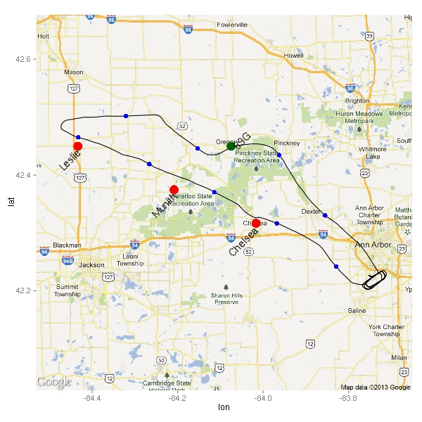
Much better! Only 26 points total, 13 below 2000 feet. Where did these points happen? (Excuse the low-resolution of the map.) You can also see the path I flew — taking off from runway 6, making a left turn to fly west to the practice area.
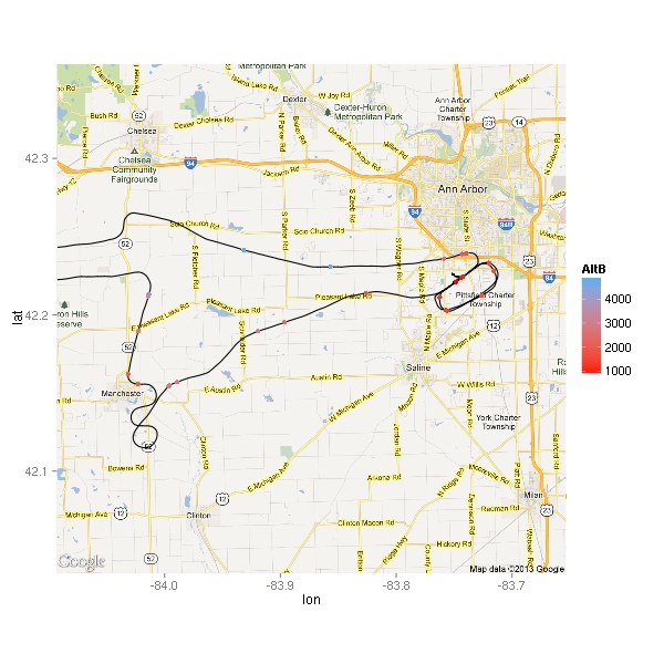
The moment I took off, I noticed that the  thermals were not going to make this a nice smooth ride. I think that’s why there are at least three points right by the highway while I was still climbing out of KARB. The air did get smoother higher up, but it still wasn’t a nice calm flight like the ones I’ve gotten used to during the winter. Looking at the map, I wonder if some of these points were due to abrupt power changes.
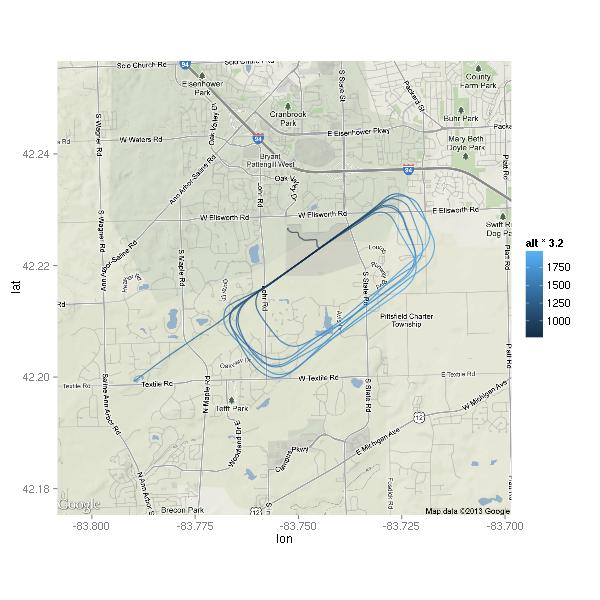
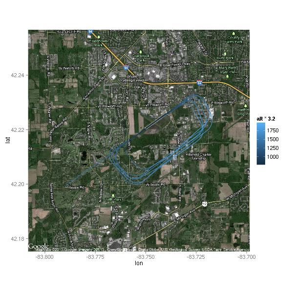
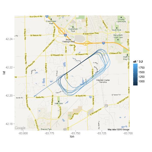
Here’s a close-up on the airport. This time, the point color indicates the amount of acceleration.
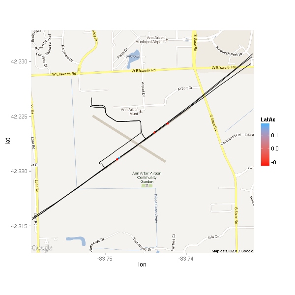
There are only 4 points displayed. Interestingly, three of the four points are negative. Let’s take a look.
                    Time LatAc  AltB  E1RPM
2594 2013-05-25 12:52:10 -0.11 879.6 2481.1
2846 2013-05-25 12:56:31 -0.13 831.6  895.8
2847 2013-05-25 12:56:32  0.18 831.6  927.4
2865 2013-05-25 12:56:50 -0.13 955.6 2541.5
The middle two are a second apart. Based on the altitude, it looks like the plane was on the ground. Based on the engine RPMs, it looks like it was within a second or two of touchdown. Chances are that it was just nose not quite aligned with the direction of travel. The other two points are likely thermals tossing the plane about a bit — the first point is from about 50 feet above ground the last is from about 120 feet. Ok, I’m curious…
> data[c(2835:2850),c("Time","LatAc","AltB","E1RPM","GndSpd")]
                    Time LatAc  AltB  E1RPM GndSpd
2835 2013-05-25 12:56:20 -0.02 876.6 1427.9  66.71
2836 2013-05-25 12:56:21  0.01 873.6 1077.1  65.71
2837 2013-05-25 12:56:22  0.01 864.6  982.4  64.21
2838 2013-05-25 12:56:23  0.04 861.6  994.1  62.77
2839 2013-05-25 12:56:24  0.01 858.6  982.6  61.54
2840 2013-05-25 12:56:25  0.01 852.6  988.2  60.18
2841 2013-05-25 12:56:26 -0.02 845.6  959.0  58.91
2842 2013-05-25 12:56:27  0.00 846.6  945.5  57.73
2843 2013-05-25 12:56:28  0.01 844.6  930.9  56.53
2844 2013-05-25 12:56:29  0.10 834.6  908.0  55.16
2845 2013-05-25 12:56:30 -0.01 827.6  886.6  54.16
2846 2013-05-25 12:56:31 -0.13 831.6  895.8  52.71
2847 2013-05-25 12:56:32  0.18 831.6  927.4  51.49
2848 2013-05-25 12:56:33 -0.06 831.6  982.0  50.21
2849 2013-05-25 12:56:34  0.05 840.6 1494.0  49.39
2850 2013-05-25 12:56:35 -0.07 833.6 2249.7  48.76
The altitudes look a little out of whack, but otherwise it makes sense. #2835 was probably the time throttle was pulled to idle. Between #2848 and #2849 throttle went full in. Ground was most likely around 832 feet and touchdown was likely at #2846 as I guessed earlier.
Let’s plot the engine related values. First up, engine RPMs.
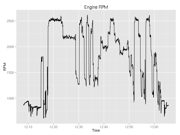
It is pretty boring. You can see the ~800 during taxi; the 1800 during the runup; the 2500 during takeoff; 2200 during cruise; and after 12:50 you can see the go-around, touch-n-go, and full stop.
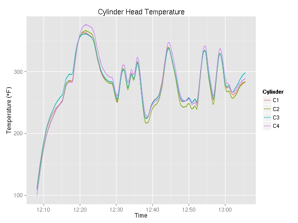
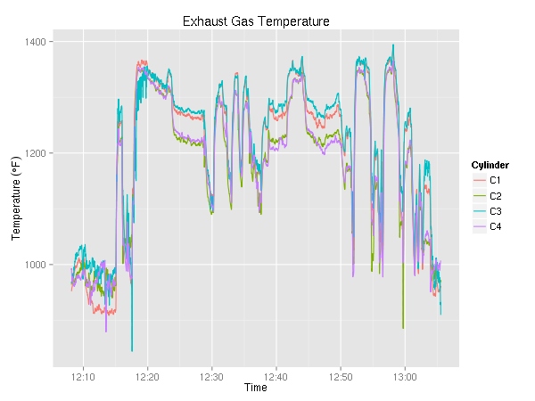
Next up, cylinder head temperature (in °F) and exhaust gas temperature (also in °F). Since the plane has a 4 cylinder engine, there are four lines on each graph. As I was maneuvering most of the time, I did not get a chance to try to lean the engine. On a cross country, it be pretty interesting to see the temperature go up as a result of leaning.
Moving on, let’s look at fuel consumption.
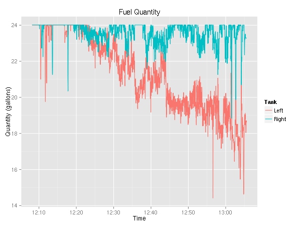
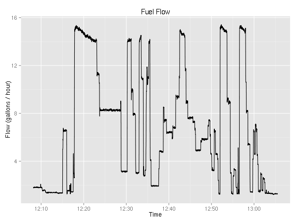
This is really weird. For the longest time, I knew that the plane used more fuel from the left tank, but this is the first time I have solid evidence. (Yes, the fuel selector was on “Both”.) The fuel flow graph is rather boring — it very closely resembles the RPM graph.
Ok, two more engine related plots.
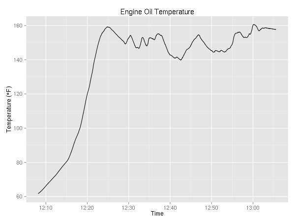
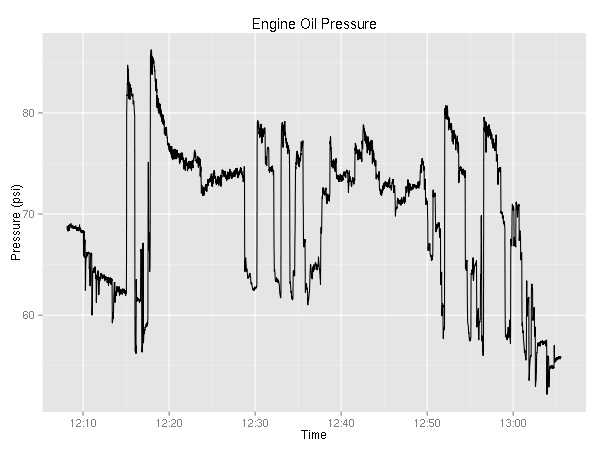
It is mildly interesting that the temperature never really goes down while the pressure seems to be correlated with the RPMs.
There are two variables with the vertical speed — one is GPS based while the other is barometer based.
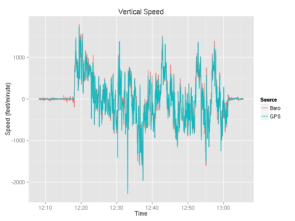
As you can see, the two appear to be very similar. Let’s take a look at the delta. In addition to just a plain old subtraction, you can see the 60-second moving average.
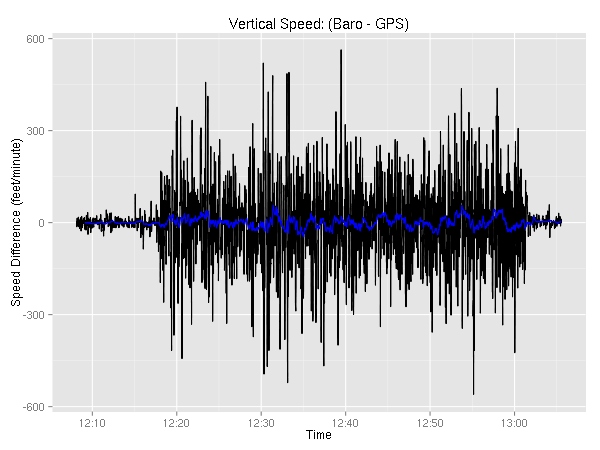
Not very interesting. Even though the two sometimes are off by as much as 560 feet/minute, the differences are very short-lived. Furthermore, the differences are pretty well distributed with half of them being within 50 feet.
> summary(data$VSpd - data$VSpdG)
     Min.   1st Qu.    Median      Mean   3rd Qu.      Max.
-559.8000  -49.2800    0.4950    0.8252   53.0600  563.4000
> summary(SMA(data$VSpd - data$VSpdG),2)
     Min.   1st Qu.    Median      Mean   3rd Qu.      Max.      NA's
-240.2000  -22.2200    0.6940    0.8226   25.4700  226.7000         9
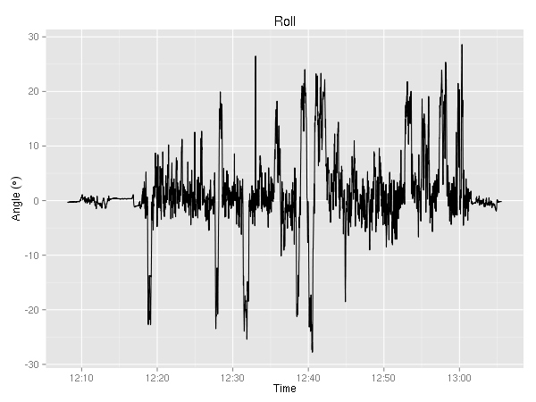
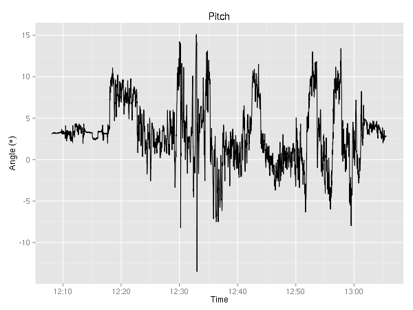
Ok, last but not least the CSV contains the pitch and roll angles. I’ll have to think about what sort of creative analysis I can do. The only thing that jumps to mind is the mediocre S-turn around 12:40 where the roll changed from about 20 degrees to -25 degrees.
I completely ignored the volts and amps variables (for each of the two busses), all the navigation related variables (waypoint identifier, bearing, and distance,  HSI source, course,
  CDI/
CDI/ GS deflection), wind (direction and speed), as well as ground track, magnetic heading and
  variation, GPS fix (it was always 3D), GPS horizontal/vertical alert limit, and WAAS GPS horizontal/vertical protection level (I don’t think the avionics can handle WAAS — the columns were always empty). Additionally, since I wasn’t using the autopilot, a number of the fields are blank (Autopilot On/Off, mode, commands).
Ideas
A while ago I learned about CloudAhoy. Their iPhone/iPad app uses the GPS to record your flight. Then, they do some number crunching to figure out what kind of maneuvers you were doing. (I contacted them a while ago to see if one could upload a GPS trace instead of using their app, sadly it was not possible. I do not know if that has changed since.) I think it’d be kind of cool to write a (R?) script that’d take the G1000 recording and do similar analysis. The big difference is the ability to use the great number of other variables to evaluate the pilot’s control of the airplane — ranging from coordinated flight and dangerous maneuvers (banking too aggressively while slow), to “did you forget to lean?”.
Update (2016-10-10): Out of the blue, I got an email from the CloudAhoy guys letting me know that a lot has changed since I wrote this post three and a half years ago and that they support uploading of lots of different flight data file formats. They seem to have some very interesting ways of visualizing the data. I think I’ll have to play with it in the near future.
 pilotage being the purpose of this exercise, and not planning on going all the way to KFPK anyway, we just decided to stay at 3000. At one point, 3000 seemed like a bit too close to the clouds, so I ended up at 2900. Below is the altitude graph. For your convenience, I plotted horizontal lines at 2800, 2900, 3000, and 3100 feet. (Near the end, you can see 4 touch and gos and a full stop at KARB.)
 VOR and estimated that the 50 degree radial would go through Munith. While that wouldn’t give me my location, it would tell me when I was abeam Munith. Shortly after, I changed my estimate to the 60 degree radial. (It looks like 65 is the right answer.)


