Scribbled Dummy Load Blueprints
Yesterday, I saw KM1NDY’s blog post titled Scribbled Antenna Blueprints. I wasn’t going to comment…but here I am. :)
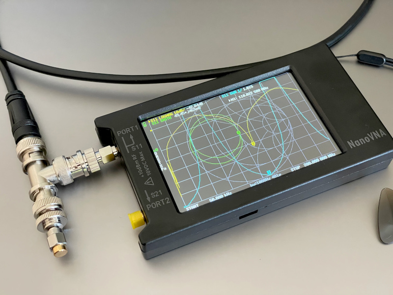
I thought I’d setup up a similar contraption (VHF instead of HF) to see what exactly happens. I have a 1 meter long RG-8X jumper with BNC connectors, a BNC T, and a NanoVNA with a 50Ω load calibration standard.
But first, let’s analyze the situation!
Imagine you have a transmitter/signal generator and you connect it to a dummy load. Assuming ideal components, absolutely nothing would get radiated. Now, imagine inserting an open stub between the two. In other words, the T has the following connections:
- the generator
- 50Ω load
- frequency-dependant impedance
Let’s do trivial math! Let’s call the total load that the generator sees and the impedance provided by the stub . The generator side of the T is connected to the other ports in parallel. Therefore:
So, when would we get a 1:1 SWR? When the generator sees a 50Ω load. When will it see 50Ω? When is very large; the extreme of which is when that side of the T is open.
If you are a ham, you may remember from when you were studying for the Amateur Extra exam that transmission line stubs can transform impedance. A 1/2 wave stub “copies” the impedance. A 1/4 wave stub “inverts” the impedance. For this “experiment” we need a high impedance. We can get that by either:
- open 1/2 wave stub
- shorted 1/4 wave stub
Since the “design” from the scribble called for an open, we’ll focus on the 1/2 wave open stub.
Now, back to the experiment. I have a 1 m long RG-8X which has a velocity factor of 0.78. So, let’s calculate the frequency for which it is a 1/2 wave—i.e., the frequency where the wavelength is 2 times the length of the coax:
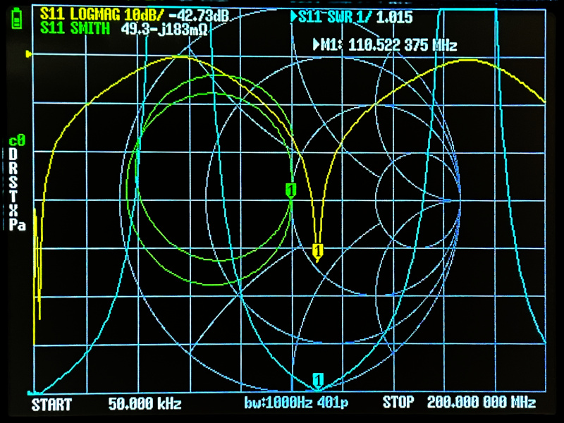
This equals 116.9 MHz. So, we should expect 1:1 SWR at 117-ish MHz. (The cable is approximately 1 m long and the connectors and the T add some length, so it should be a bit under 117.)
Oh look! 1.015:1 SWR at 110.5 MHz.

(Using 1.058 m in the calculation yields 110.5 MHz. I totally believe that between the T and the connectors there is close to 6 cm of extra (electrical) length.)
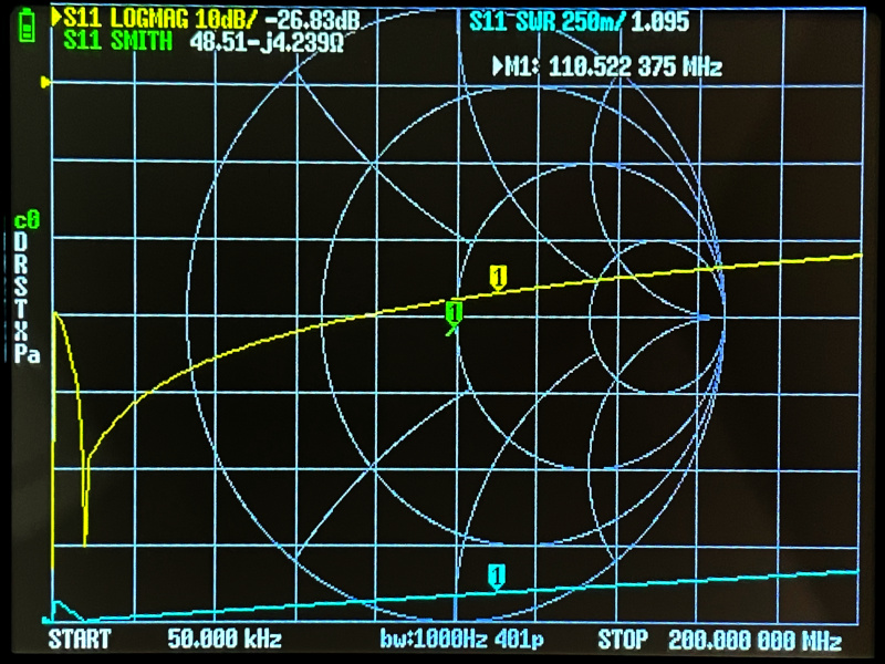
But wait a minute, you might be saying, if high impedance is the same as an open, couldn’t we just remove the coax stub from the T and get the same result? Yes! Here’s what the NanoVNA shows with the coax disconnected:

The SWR is 1.095:1 at 110.5 MHz and is better than 1.2:1 across the whole 200 MHz! And look at that impedance! It’s about 50Ω across the whole sweep as well!
We can simplify the circuit even more: since we’re only using 2 ports of the T, we can take the T out and connect the 50Ω load to the NanoVNA directly. We just saved $3 from the bill of materials for this “antenna”!
(In case it isn’t obvious, the previous two paragraphs were dripping with sarcasm, as we just ended up with a dummy load connected to the generator/radio and called it an antenna.)
Will It Antenna?
How could a dummy load transmit and receive signals? Glad you asked. In the real world we don’t use ideal components. There are small mismatches between connectors, the characteristic impedance of the coax is likely not exactly 50Ω, the coax shield is not quite 100%, the transmitter’s/generator’s output isn’t exactly 50Ω, and so on.
However, I expect all these imperfections do not amount to anything that will turn this contraption into an antenna. I bet that the ham that suggested this design used an old piece of coax which had even worse characteristics than the “within manufacturing tolerances” specs you get when the coax is new. Another option is that the coax is supposed to be connected in some non-standard way. Mindy accidentally found one as she was packing up when she disconnected the shield but not the center conductor. Either way, this would make the coax not a 1/2 wave open stub, and the resulting impedance mismatch would cause the whole setup to radiate.
I’d like to thank Mindy for posting about this design. It provided me with a fun evening “project” and a reason to write another blog post.
Finally, I’ll leave you with a photo of my experimental setup.
