Last summer I ended up getting licensed as a  radio amateur. (Yes, it took me 11 months to mention it here.) Since then, I’ve been keeping myself busy trying out various aspects of the hobby. A week and a half ago, I got to combine a few of these aspects and participate in the ARRL June VHF contest. Namely, I wanted to try combining: contesting, roving, operating from a park, and antenna building.
I’ve been meaning to try roving for the past 7 months, but every time there was a good opportunity (in other words a VHF contest), life got in the way and I couldn’t participate.
Since I first got the idea, I’ve emailed with a number of people about a variety of radio-related topics. Speaking specifically of VHF contest roving, WB8LYJ and WW7D provided me with plenty of information. As a matter of fact, they gave me so much roving info I didn’t even use it all—yet. Thank you!
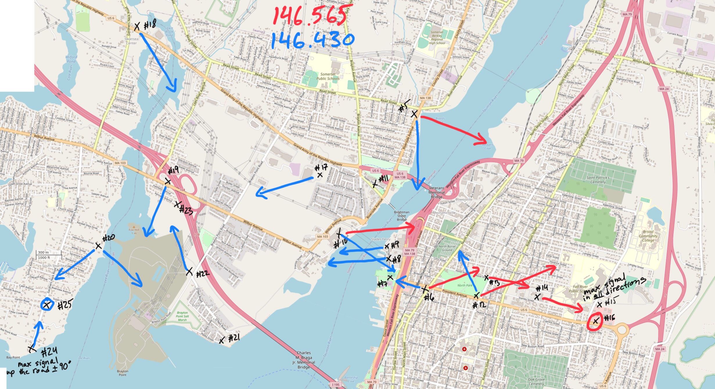
Location Planning
Every rove starts with planning of the route. In order to be a rover, one must make contacts from at least two grid squares during the contest. Given that this was going to be my first rove, I decided to do the bare minimum and visit only two grids to get some experience for the next time.
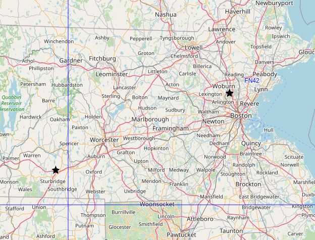
I live in FN42, so I went with a location I knew would work—the Middlesex Fells Reservation. I’ve been there a couple of times, so I knew exactly which hill I wanted to use. This requires a 200 m hike with about 15 m of elevation gain to get to from the parking lot.
Living pretty much in the center of FN42, I have three equally annoying options for the second grid—FN32 to the west, FN43 to the north, and FN41 to the south.
I looked for parks just outside FN42 to operate from and eventually settled on Wells State Park in Sturbridge, MA in FN32.
At VHF and UHF frequencies, the elevation of the antennas matters quite a bit, so I was happy to see that Wells State Park has a decent hill—Carpenter’s Rocks. The peak is at about 260 m while the parking lot at the bottom of the park is at 190 m—or about 70 m of elevation gain over 1.1 km of distance. Hiking up the hill with the necessary radio equipment didn’t seem like too crazy of an idea while sitting at my computer.
Finally, both Wells and Middlesex Fells are in the Parks on the Air and World Wide Flora & Fauna databases. Wells is K-2462 and KFF-2462, while Middlesex Fells is K-8414 and KFF-5690, respectively. So, not only do any contacts made there count toward the contest, I can also use them to get credit for activating the parks. (Well, I didn’t realize that Wells was a WWFF park until after the contest.)
To keep the timing simple, I was going to spend Saturday at Wells and Sunday at Middlesex Fells.
Antenna—2 m
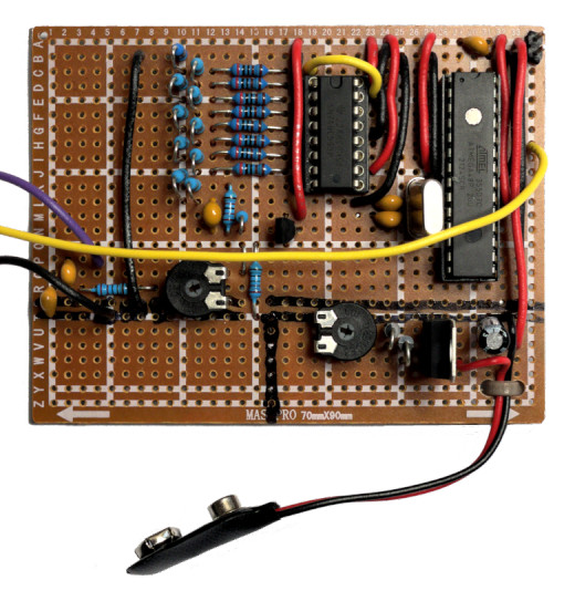
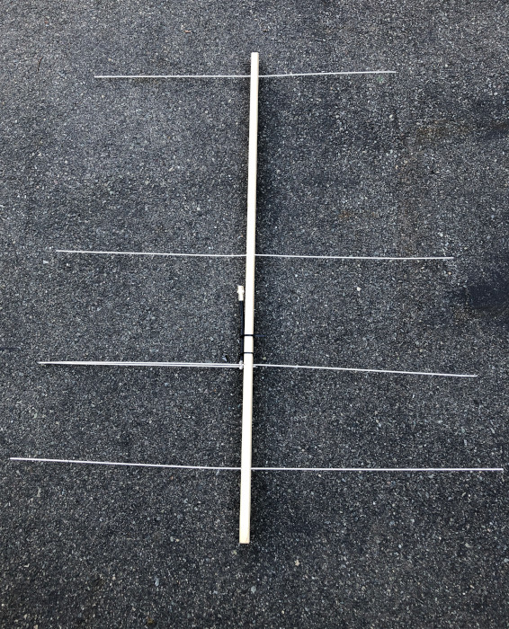
The plan for a few months was to build yagis for 2 m and 70 cm bands and some (weakly) directional antenna for the 6 m band. Somehow, I ran out of time and only managed to build the 2 m yagi the day of the contest.
I went with WA5VJB’s cheap yagi design. I used a 2 inch by 1 inch wooden furring strip for the boom and 1/8 inch aluminum tubes for the elements.
Here’s the antenna after the contest. The elements are beaten up and slightly misaligned.
Boom
I bought an 8 foot long furring strip and cut it in half, which gives plenty of space as the 4-element “cheap yagi” design requires 40.5 inches between the reflector and the second director. I placed the reflector about 5 inches from the end of the boom which leaves enough room to act as a hand grip. This left about 2 inches extra on the other end.
Because I didn’t have time to figure out how to attach it to a mast, I drilled 3/8 inch holes about 1 inch from both ends of the boom to let me suspend it on a rope from a tree branch.
Elements
The aluminum tubes I found come in 3 foot sections. Unfortunately, three of the four elements in the design are longer than 3 feet, so I had to splice them together to make the longer lengths.
At the hardware store, I noticed that the 3/32 inch aluminum tube fit nicely (but loosely) inside the 1/8 inch tubes. So, the plan was to use bits of the smaller diameter tube as a stub to hold the sections together.
At first, I tried to solder the sections together, but the solder just wasn’t sticking to the aluminum. After nearly giving up on the build, I realized that I can crimp the pieces together. The 0.100 hex die I have for coax crimping works perfectly for this.
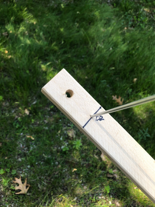
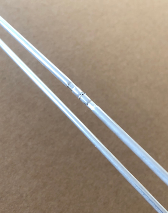
So, whenever I needed to do a splice, I’d insert a 1 inch section of the 3/32 inch aluminum tube between the two section of 1/8 inch tube to be joined and I’d crimp each side. This provides decent mechanical and electrical connections.
Completed splice on the driven element:
Fragility
Unfortunately, the aluminum tubes themselves are rather fragile. While carrying the fully built yagi up and down a hill, it was far too easy to bump one of the elements and bend it immediately next to the boom. It didn’t take many bumps for metal fatigue to result in a break. Thankfully, the one and only break happened on the way home. I still had to fix it in order to use the antenna on the second day of the contest.
I would not recommend 1/8 inch aluminum tubes for 2 m yagis. The elements stick out a bit too much. Combine that with the softness of aluminum, and you have an antenna that’ll break far too easily. A yagi for 70 cm might be narrow enough that these aluminum tubes would work well, but I haven’t tried. I plan to repurpose the tubes from this build for a 10-element 1296 MHz yagi. With the widest element being only 4.3 inches, it should be relatively robust. And if one of the elements breaks, it is simple enough to just cut a new one instead of having to splice things back together.
Antenna—6 m
For the 6 m band, I reused my 1/4 wave vertical that I’ve been using for Parks On The Air activations over the past two months. (I plan on making a separate post about my 1/4 wave verticals.)
Antenna—70 cm
I don’t have a dedicated 70 cm antenna. However, I have an Ed Fong DBJ-1, which is a 2 m/70 cm wire J-pole antenna. It only really works on the 440-450 MHz part of the band, but it is better than nothing.
Contest Itself
Unsurprisingly, not everything went according to plan.
Suspending the yagi from a branch worked, but it was a bit fiddly. Specifically, it was far too easy to tilt it up or down instead of keeping it level. It was also a bit difficult to aim the antenna in a specific direction since the coax hanging down constantly tried to turn it back to where it started.
Saturday
The contest started at 18:00Z. I planned to leave early enough that I could drive over to Wells State Park, grab all the gear, hike up the hill, set up, test everything, and then have a few minutes to relax before the start.
Well, I ended up leaving late because of last minute antenna building. I planned to leave about two hours before the start of the contest, but managed to leave only 5 minutes before the start.
I arrived at the park, and it became obvious that I wasn’t quite sure how to get to the top of the hill. Instead of roaming aimlessly around the forest with all the gear, I did a quick hike to the top to find a reasonable way. This extra hiking added another 30 minute delay to my start.
When I got back to the car, I grabbed everything and headed up again. The second ascent was much harder because of the ~16 kg (~35 lbs) of radios, coax, battery, water, etc. Having my hands literally full also made it harder to defend myself from mosquitoes on the way up. Thankfully, the top of the hill didn’t have any.
Once back at the top, I took a few minutes to reduce my heart rate and then I started setting up. That’s when I discovered that even though I brought three antennas with me, I hauled only two coaxes up the hill. I left the third (and spare fourth) in the car. There was no way I was going to go back to the car, so I resorted to moving one of the coaxes between the Ed Fong and the 6 m 1/4 wave. During the first coax swap, I realized that I also forgot a coax switch.
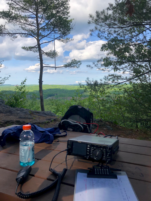
Anyway, at least the view was nice. (You can see the Ed Fong antenna hanging in the tree on the left.)
At 00:00Z, about 20 minutes before sunset, I called it a day, packed up, and descended through the mosquito territory once more to get to the car. During the descent, I managed to break off one of the elements on the yagi.
Sunday
The first thing I did Sunday morning was fix the yagi. This took extra effort because the break happened at a crimped joint. So, the first step was to remove the broken inner aluminum tube. Once removed, re-crimping took very little time.
After that, eating breakfast, repacking everything, and so on, I headed out to Middlesex Fells. I hiked up the hill, set up the three antennas, and started working stations around noon (16:00Z).
I’m not sure what happened, but I think the repair I did on the yagi or something else messed up its pattern. It seemed as if the pattern rotated 20-30 degrees.
I planned to stay about 8 hours—from noon to 8pm (16:00Z–00:00Z), but about half way through the breeze died down enough that the mosquitoes started biting. It was nowhere near as bad as during the hikes at Wells, but enough that by 5pm (17:00Z) I decided to call it quits. I packed up and headed home. On the way home, I realized that I could use my handheld radio to catch a few more FM contacts by going to Robbins Farm Park. It is near home, has good elevation, and overlooks Boston, Cambridge, etc. — in other words, places with people and therefore hams.
I made it up to Robbins Farm Park about an hour later. I called for good 25 minutes before I got a response. The person that got back to me happens to be a new-ish ham. We chatted for about half an hour about antenna building, portable operations, ham radio in general, software (we’re both software developers), and programming languages. After that contact, I decided that I wanted dinner and went home.
Preliminary Results
So, how did I do? I ended up with a score of 832 points. Not great, but not bad either.
In more detail, I…
- worked in 2 grids (FN32 and FN42)
- worked 7 unique grids (EL98, FN31, FN32, FN33, FN41, FN42, and FN43)
- made 49 SSB/FM contacts (3 on 70 cm, 32 on 2 m, and 14 on 6 m)
Improvements For Next Time
I definitely learned quite a bit about about VHF contesting and roving. None of it is ground breaking, and I’ve heard some variant of each of my conclusions before, but I can confirm that they are valid ideas. :)
- I should have a beam for every band I plan to use.
- I should remember to ask the other person which bands they can use.
- I should visit more grids.
- I should share the itinerary with people in the area that are interested in the contest.
- I should avoid (long) hikes.
- I should make antenna setup as fast as possible.
- I should use a mast instead of suspending antennas from trees.
The next relevant contest is the CQ World Wide VHF Contest in July. Which means that I have a month to rebuild the 2 m yagi, construct something directional for 6 m that is still easy enough to transport, and figure out a mast. I should also start scoping out locations. Finally, I need to subscribe to some mailing lists so I have a place to announce my intentions.
Results
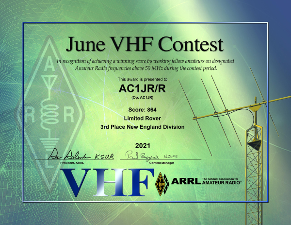
This section has been added in November 2021. The results for the contests are out.
With 864 points, I placed 3rd in the New England division. This sounds impressive, but there were only 4 limited rovers in New England. More impressively, I placed 36th out of 62 limited rovers in all of US.