Josef “Jeff” Sipek

Scribbled Dummy Load Blueprints

Yesterday, I saw KM1NDY’s blog post titled Scribbled Antenna Blueprints. I wasn’t going to comment…but here I am. :)

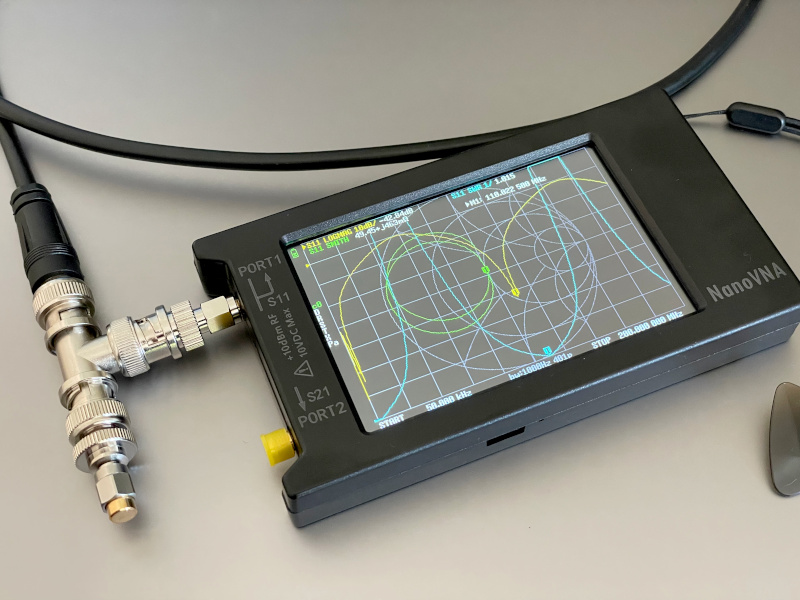
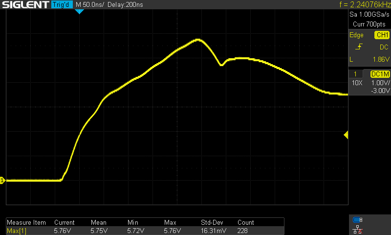
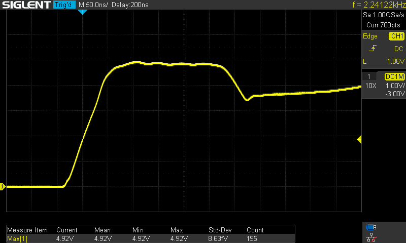
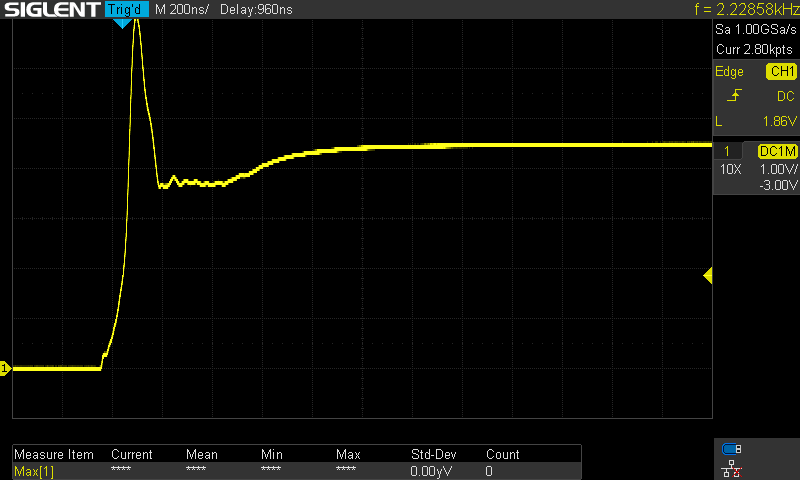
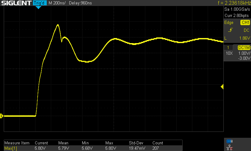
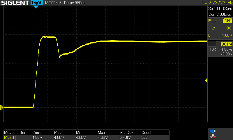
I thought I’d setup up a similar contraption (VHF instead of HF) to see what exactly happens. I have a 1 meter long RG-8X jumper with BNC connectors, a BNC T, and a NanoVNA with a 50Ω load calibration standard.

But first, let’s analyze the situation!

Imagine you have a transmitter/signal generator and you connect it to a dummy load. Assuming ideal components, absolutely nothing would get radiated. Now, imagine inserting an open stub between the two. In other words, the T has the following connections:

  1. the generator
  2. 50Ω load
  3. frequency-dependant impedance

Let’s do trivial math! Let’s call the total load that the generator sees Ztotal and the impedance provided by the stub Zstub. The generator side of the T is connected to the other ports in parallel. Therefore:

Ztotal=50*Zstub50+Zstub

So, when would we get a 1:1 SWR? When the generator sees a 50Ω load. When will it see 50Ω? When Zstub is very large; the extreme of which is when that side of the T is open.

If you are a ham, you may remember from when you were studying for the Amateur Extra exam that transmission line stubs can transform impedance. A 1/2 wave stub “copies” the impedance. A 1/4 wave stub “inverts” the impedance. For this “experiment” we need a high impedance. We can get that by either:

  1. open 1/2 wave stub
  2. shorted 1/4 wave stub

Since the “design” from the scribble called for an open, we’ll focus on the 1/2 wave open stub.

Now, back to the experiment. I have a 1 m long RG-8X which has a velocity factor of 0.78. So, let’s calculate the frequency for which it is a 1/2 wave—i.e., the frequency where the wavelength is 2 times the length of the coax:

f=0.78*c/2m

This equals 116.9 MHz. So, we should expect 1:1 SWR at 117-ish MHz. (The cable is approximately 1 m long and the connectors and the T add some length, so it should be a bit under 117.)

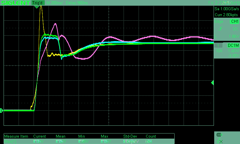
Oh look! 1.015:1 SWR at 110.5 MHz.

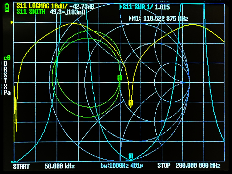
(Using 1.058 m in the calculation yields 110.5 MHz. I totally believe that between the T and the connectors there is close to 6 cm of extra (electrical) length.)

But wait a minute, you might be saying, if high impedance is the same as an open, couldn’t we just remove the coax stub from the T and get the same result? Yes! Here’s what the NanoVNA shows with the coax disconnected:

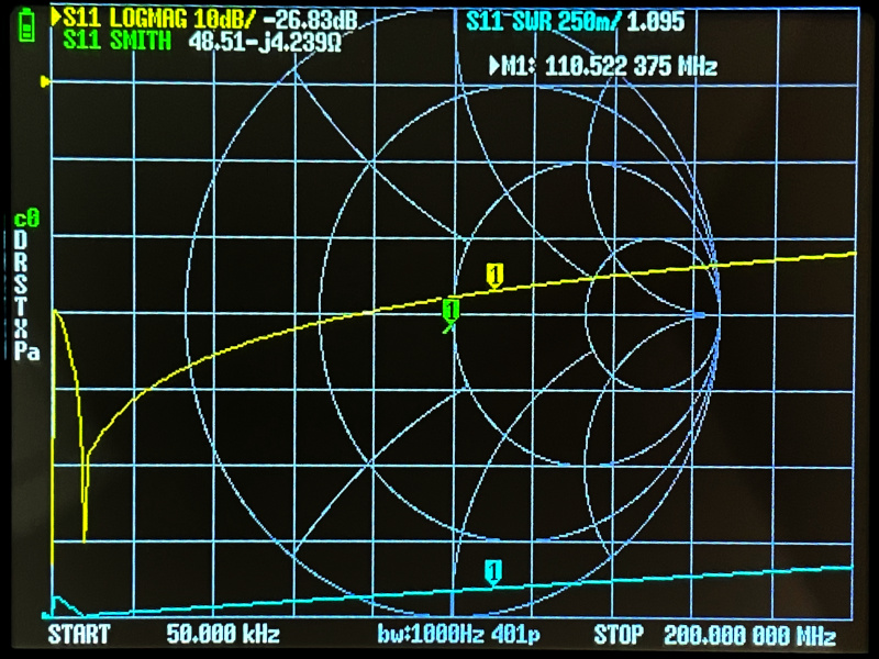
The SWR is 1.095:1 at 110.5 MHz and is better than 1.2:1 across the whole 200 MHz! And look at that impedance! It’s about 50Ω across the whole sweep as well!

We can simplify the circuit even more: since we’re only using 2 ports of the T, we can take the T out and connect the 50Ω load to the NanoVNA directly. We just saved $3 from the bill of materials for this “antenna”!

(In case it isn’t obvious, the previous two paragraphs were dripping with sarcasm, as we just ended up with a dummy load connected to the generator/radio and called it an antenna.)

Will It Antenna?

How could a dummy load transmit and receive signals? Glad you asked. In the real world we don’t use ideal components. There are small mismatches between connectors, the characteristic impedance of the coax is likely not exactly 50Ω, the coax shield is not quite 100%, the transmitter’s/generator’s output isn’t exactly 50Ω, and so on.

However, I expect all these imperfections do not amount to anything that will turn this contraption into an antenna. I bet that the ham that suggested this design used an old piece of coax which had even worse characteristics than the “within manufacturing tolerances” specs you get when the coax is new. Another option is that the coax is supposed to be connected in some non-standard way. Mindy accidentally found one as she was packing up when she disconnected the shield but not the center conductor. Either way, this would make the coax not a 1/2 wave open stub, and the resulting impedance mismatch would cause the whole setup to radiate.

I’d like to thank Mindy for posting about this design. It provided me with a fun evening “project” and a reason to write another blog post.

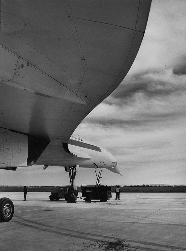
Finally, I’ll leave you with a photo of my experimental setup.

555 Timer Comparison

In the late 90s, I messed a little bit with electronics but I stopped because I got interested in programming. This last January, I decided to revisit this hobby.

I went through my collection of random components and found one 555 timer chip—specifically a TS555CN. I played with it on a breadboard and very quickly concluded that I should have more than just one. Disappointingly, sometime over the past 25 years, STM stopped making TS555 in DIP packages, so I ordered NA555PE4s thinking that they should be similar enough.

When they arrived, I tried to make use of them but I quickly noticed that their output seemed…weird. I tweeted about it and then tweeted some more. I concluded that precision 555s just weren’t fundamental enough to most circuits using DIP packages, and that I would have to make do with the NA555 parts.

Fast forward a few months, and I noticed ICM7555IPAZ on Mouser. The datasheet made it look a lot like the TS555…so I bought one to benchmark.

I went with a very simple astable multivibrator configuration—the same one that every 555 datasheet includes:

R1, R2 1kΩ
C1 220nF
C2 0.01μF
C3 10μF

The TS555 datasheet suggested 0.01μF for C2, and it didn’t seem to harm the other two chips so I went with it.

The NA555 datasheet suggested 0.01μF for C3. That cleaned up the rising edge slightly for TS555 and ICM7555. NA555’s rising edge actually became an edge instead of a huge mess, however it still seemed to be limited so I went with a bigger decoupling capacitor—namely 10μF. That didn’t seem to harm the other two chips.

Finally, note that the output is completely unloaded. I figure that this is reasonable since there are plenty of high input impedance loads that the 555 output could feed into. (A quick sanity check with a 1kΩ resitor to ground shows that the output voltage drops by about a volt, but the general shape of the wave doesn’t change.)

I assembled it on a breadboard with plenty of space for my fingers to swap out the chip:

The orange and red wires go to +5V and the black one goes to ground. All 3 are plugged in just right of the decoupling capacitor (off image).

Looking at the three datasheets, they all provide the same (or slightly rearranged) formulas for the frequency and duty cycle. Since I used 1kΩ for the two resistors and 220nF for the capacitor, I should be seeing:

f=1.44(RA+2*RB)*C=2182Hz

and duty cycle:

D=RA+RBRA+2*RB=23 or 66.67%

Because I used a breadboard, there is some amount of stray capacitance which likely shifts the frequency a bit. Based on previous experience, that shouldn’t be too much of an issue.

I supplied the circuit with a power supply set to 5V and 0.2A. (It operated in constant-voltage mode the entire time.)

Unlike some of my previous experiments, I actually tried to get a nice clean measurement this time. I used the probe grounding spring to get a short ground and measured between pin 1 and 3 (ground and output, respectively).

Let’s look at the amplitude, frequency, duty cycle, and rise time of the three chips. I took screenshots of the scope as I was performing the various measurements. To make it easier to compare them, I made combined/overlayed images and tweaked the colors. This makes the UI elements in the screenshot look terrible, but it is trivial to see how the chips compare at a glance. In the combined images TS555 is always yellow, NA555 is cyan, and ICM7555 is magenta.

Amplitude, frequency, and duty cycle

(Individual screenshots: NA555, TS555, ICM7555)

It is easy to see that the output of both TS555 and ICM7555 goes to (and stays at) 5V. The NA555 spikes to 5V during the transition, but then decays to 4.5V. More on this later.

Similarly, it is easy to see that the TS555 and NA555 have a very similar positive cycle time but different enough negative cycle time that their frequencies and duty cycle will be different.

TS555 got close with the frequency (2.20 kHz) while NA555 got close with the duty cycle (65.75%). ICM7555 was the worst of the bunch with 2.28 kHz and 63.23% duty cycle.

Rise time

(Individual screenshots: NA555, TS555, ICM7555)

The NA555 has a comparatively awful rise time of 74.88 ns. The TS555 appears to be a speed demon clocking in at 18.69 ns. Finally, the ICM7555 appears to split the difference with 41.91 ns.

I still think that it is amazing that a relatively inexpensive scope (like the Siglent SDS 1104X-E used for these measurements) can visualize signal changes on nanosecond scales.

Revisiting amplitude

In a way, looking at the amplitude is what got me into this evaluation—specifically, the strange output voltage on the NA555 chip. Let’s take a look at the first microsecond following a positive edge.

(Individual screenshots: NA555, TS555, ICM7555)

After the somewhat leisurely rise time of ~75 ns, the output stays near 5V for about 200 ns, before dipping down to about 3.75V for almost 200 ns and then recovering to about 4.5V over the next 400 ns. The output stays at 4.5V until the negative edge.

This is weird and I don’t have any answers for why this happens. I tried a handful of the NA555s (all likely from the same batch), and they all exhibit this behavior.

NA555 decoupling

As I mentioned in the introduction, I didn’t follow the NA555’s decoupling capacitor suggestion. I wasn’t planning on writing this section, but I think that it is interesting to see just how much the output changes as the decoupling capacitor is varied.

As before, I made combined/overlayed images for easier comparison. This time, yellow is no decoupling capacitor, magenta is 0.01μF (suggested by the NA555 datasheet), cyan is 0.1μF, and green is 10μF (used in chip comparison circuit).

(Individual screenshots: no cap, 0.01μF, 0.1μF, 10μF)

As you can see, not having a decoupling capacitor makes the output voltage go to nearly 7V in a circuit with a 5V supply. Adding the suggested 0.01μ certainly makes things better (the peak is at about 5.8V) but it looks like the chip is still struggling to deal with the transient. Using 0.1μF or more results in approximately the same waveform with a peak just around 5V.

The suggested 0.01μF has another problem in my circuit. It makes the NA555’s output ring:

(Individual screenshots: no cap, 0.01μF, 0.1μF, 10μF)

Neither the TS555 nor the ICM7555 have this issue. They are both quite happy with a 0.01μF capacitor. Without any capacitor, they have a little bit of a ring around 5V (1.2Vpp for TS555, 200mVpp for ICM7555) but it subsides promptly. The ICM7555’s ringing is so minor, that it probably isn’t worth it to even use a decoupling capacitor.

Summary

I’ve collected the various measurements from the screenshots and put them into the following table:

Calculated TS555CN NA555PE4 ICM7555IPAZ
f (kHz) 2.182 2.20 (+0.8%) 2.24 (+2.7%) 2.28 (+4.4%)
D (%) 66.67 64.68 (-3.0%) 65.75 (-1.4%) 63.23 (-5.2%)
Rise (ns) 18.69 74.88 41.91
Logic high peak (V) 5 5.08 5.12 5.08
Logic high steady state (V) 5 5.08 ~4.5 5.08

So, what does this all mean? Ultimately, not a whole lot. The 555 is a versatile chip, but not a magical one. Despite what the NA555 datasheet says, the 555 is not a precision device by modern standards, but it is still an easy way to get a square(-ish) wave around the desired frequency.

With that said, not all 555s are created equal.

The NA555 with all its flaws still works well enough and has a low price. So, for any sort of “crude” timing, it should work well. If, however, the circuit making use of the timer output requires a cleaner signal, then I’d reach for something better.

The ICM7555 is very good. It produces a nice clean output with reasonably fast edges, but not as fast as the TS555. Unfortunately, the performance costs extra—an ICM7555 is about twice the cost of a NA555.

All things being equal, the TS555 and ICM7555 are on par. One has a faster edge, the other has less ringing (and is still actively manufactured). I’ll save the TS555 for future benchmarks. Depending on the application, I’ll either use a NA555 or ICM7555.

IFR Alternate Minimums

As some of you already know, I’ve been working on my instrument rating over the past 5–6 months. As part of it, I had to figure out and understand the regulations governing when an alternate airport is needed and the required weather at the destination and alternate airports.

The first part is answered by 91.169(a) and 91.169(b). To give you taste of the regulations, here is (b):

(b) Paragraph (a)(2) of this section does not apply if:

(1) Part 97 of this chapter prescribes a standard instrument approach procedure to, or a special instrument approach procedure has been issued by the Administrator to the operator for, the first airport of intended landing; and

(2) Appropriate weather reports or weather forecasts, or a combination of them, indicate the following:

(i) For aircraft other than helicopters. For at least 1 hour before and for 1 hour after the estimated time of arrival, the ceiling will be at least 2,000 feet above the airport elevation and the visibility will be at least 3 statute miles.

(ii) For helicopters. At the estimated time of arrival and for 1 hour after the estimated time of arrival, the ceiling will be at least 1,000 feet above the airport elevation, or at least 400 feet above the lowest applicable approach minima, whichever is higher, and the visibility will be at least 2 statute miles.

Clear as mud, isn’t it?

The second question (the required weather at the destination and alternate airports) is answered by 91.169(c). Don’t worry, I won’t quote it here.

Since the text of the regulation is not easy to read, I decided that the best way to understand it is to make a flowchart. As I fly airplanes, I’ve ignored any part of the regulations that is about aircraft other than airplanes.

The result:

Clearer? I certainly think so!

The one big thing to keep in mind about this flowchart is that not every approach can be used during planning. This is a semi-large topic of its own.

In short, any approach that you aren’t authorized for, the plane isn’t equipped for, or that has a NOTAM saying that it isn’t available, effectively doesn’t exist. As far as GPS approaches are concerned, if you have a TSO 129 or 196 GPS, then you have another restriction—you cannot plan on using GPS approaches at both your destination and your alternate.

I found it useful to write this down and in the process truly understand the rules. Hopefully, you’ve found this useful as well. Needless to say, you should not rely on this flowchart without verifying that it is correct. Regulations sometimes change, and people sometimes make mistakes when making flowcharts to visualize said regulations. (If you find a problem, let me know!)

One final thought: just because the regulations don’t require an alternate airport doesn’t mean that you shouldn’t have one anyway. Weather often seems to have a mind of its own and a propensity to prove forecasters wrong.

Google Traffic, iOS edition

Several years ago, I wrote about how Google gets traffic information and how to turn off this location reporting on Android phones. Since then I’ve switched to iPhones. While I normally use the built-in Maps app, I keep Google Maps installed as a fallback—just in case.

I upgraded my phone recently and so I spent some time going through all the apps and making sure they worked and didn’t have more access than necessary. This is when I discovered that the Google Maps app for iOS defaults to collecting location information and sharing it with Google. Given my previous post, this isn’t really surprising.

Turning it off

Anyway, as with the Android post, here are the steps to limit Google’s collection of location information.

First of all, in Settings → Privacy → “Location Services”, I changed Google Maps’s permission to “While Using the App”. If I’m not using the app, then it doesn’t need to know where I am.

Second, in the app itself, go to: Settings → “About, terms & privacy” → “Location data collection”. That’s right, this setting is buried in what appears to be a page with the boring legal notices.

And then turn off the the toggle:

That should do it…at least assuming that Google honors the settings in its own app.

iPhone 7 "Review"

I stopped by an Apple Store nearby, and played with the new iPhone 7 for a couple of minutes. Why? I have an iPhone 5s which is still working, but it is lacking some nice-to-have features. I got the 5s back in the day because I got fed up with my Galaxy Nexus—it got unusably slow, and I wasn’t really a fan of the screen size (it was too big). That’s right, I wanted a phone screen that was smaller so I could use it with just one hand. The iPhone 5s fit the bill perfectly.

Now, it is 2016 and the 5s is getting a bit old and the 7 just came out. Should I upgrade? The iPhone 7 is better in just about every way, but the screen…it’s bigger than the 5s’s. (Yes, I realize it’s the same as the 6 and 6s.)

Trying it out

My main goal with playing with the phone at the store was to see if I was OK with the size. I made sure to type on the keyboard both one-handed and two-handed, browse some websites (mostly scrolling around), and see which screen locations were hard to reach.

The new home button is certainly interesting. It is a fingerprint reader (this is nothing new by itself) with haptic feedback. So, “pressing” it results in a similar sensation to what the physical button provided in the previous models. It’s not the same exact feel, but it was surprisingly good. It felt like the feedback was coming from near the home button, not just the whole phone vibrating.

The phone certainly felt bigger than my current one. The test drive wasn’t long enough for me to make a determination based on this alone.

One-handed operation

While playing with the phone, I made an interesting “discovery” about my one-handed use of phones. Apparently, I hold smartphones one of two ways. If I am typing, I hold the phone further down; on the other hand, if I am mostly scrolling, I hold it closer to its center of gravity. Needless to say, this affects how far on the screen my thumb can reach.

When I’m holding the phone near the center of gravity, all icons (see above screenshot) except the top row and the Maps app are easy to reach. The Mail app is essentially impossible to reach without shifting the phone in my hand. The remaining ones are doable, but it takes more effort than just moving my thumb over.

If I’m holding the phone lower down (e.g., because I was just typing), then the top two rows of icons are hard to use—with the top left corner (i.e., Mail) being impossible to reach.

There is an accessibility option (called “Reachability”) which shifts the whole screen down 30–40%. This makes the top two rows of icons reachable. (Once enabled, trigger it by double-tapping the home button.) While it is neat that this is available, it feels a bit like a hack.

Specs

When I got home, I decided to make a table of the physical specs. Specifically, the physical dimensions, weight, and the screen size. In addition to the two iPhones, I included the Galaxy Nexus (my previous phone) and the Samsung Galaxy S7 (the current flagship Samsung Galaxy phone).

Phone Size (mm) Weight Screen
iPhone 5s 123.8 x 58.6 x 7.6 112g 100mm, 1136x640
iPhone 7 138.3 x 67.1 x 7.1 138g 120mm, 1334x750
Galaxy Nexus 135.5 x 67.94 x 9.47 135g 118mm, 1280x720
Samsung Galaxy S7 142.4 x 69.6 x 7.9 152g 130mm, 2560x1440

When I first made this table, I was surprised at how close the iPhone 7 is to the Galaxy Nexus. Size-wise within a couple of mm! Weight-wise only a 3 g difference. The good news is, I can use my 2.5 years of Galaxy Nexus use as a guide to answer my question about the iPhone size. The bad news is, I didn’t really like the screen size on the Galaxy Nexus.

Conclusion

I think the conclusion is clear—I am going to wait to see if Apple makes a smaller version over the next year. Until then, I will stick with my 5s.

Concorde

I just came across someone’s blog post full of cool Concorde photos.

It’s a hard choice, but my favorite photo is:

Concorde

(The black and white photography and the unusual camera position in these images remind me of the Wernher von Braun photo I posted years ago.)

Happy 50th, System/360

It’s been a while since I blahged about mainframes. Rest assured, I’m still a huge fan, I’m just preoccupied with other things to continuously extoll their virtues.

The reason I’m writing today is because it is the 50th anniversary of the System/360 announcement. Aside from the “50 years already?” sentiment, I have a couple of images to share. (I found these several years ago on someone’s GeoCities site. It’s a good thing I made a mirror :) )

I also came across this video from 1964:

Google Traffic

Ever wonder how Google gets its traffic information?

traffic

Apparently, there are two sources. The first is the Department of Transportation. The second consists of Android users.

You can always check Google Location History to see what sort of data Google has. (Of course, they may always have more than they show.) Seeing the data can be a bit unnerving. Since I’m not really into giving Google more data than they already have to begin with, and I see no reason for Google to know exactly where I spend my time, I decided to turn this feature off.

Turning it off

You can find the setting by running the “Google Settings” app. That’s right, not “Settings”. Once there, select “Location”.

traffic

As you can see, I want to treat Google apps like any other vendor’s apps. As an added bonus, it looks like my GPS is on way less often.

Cake

I’ve had the following draft for a very long time. It’s time to publish it already, isn’t it?

Yesterday, I came across a site dedicated to Cake Wrecks — in other words, cake decoration attempts gone wrong.

The best ones I’ve found on this site include:

Dr Who
Dr Who
Dr Who
Dr Who
Dr Who

Spiral

From 3 days ago:

This morning in arctic Norway, onlookers were stunned when a gigantic luminous spiral formed in the northern sky. Veteran observers accustomed to the appearance of Northern Lights say they have never seen anything like it. It was neither a meteor nor any known form of atmospheric optics. Rumors that the spiral was caused by the botched launch of a Russian rocket have not yet been confirmed.

Spiral
(original)

Powered by blahgd