Josef “Jeff” Sipek

End-Fed Half-Wave & 49:1 Unun

I am a happy user of 1/4 wave verticals and hamsticks, but I’ve been thinking that I should look into another antenna type to add to my bag of tricks when I go out to do a POTA/WWFF activation. The hamsticks are easy to set up and completely avoid dealing with people tripping over wires, but they aren’t as good as full-sized antennas. On the other end of the spectrum, 1/4 wave verticals work really well, but the radial field needs quite a bit of space and curious passers-by have a tendency to walk right through it.

For a long while, I was contemplating building a end-fed half-wave antenna. The draw with this type of antenna is that it has a minimal ground footprint, but it is still a full-sized antenna, so it should perform well.

Before I go any further, I should say that there is a difference between end-fed half-wave and random-wire antennas. End-fed half-waves, as the name suggests, are exactly half a wavelength long. In theory, the feed point has an infinite impedance, but in practice it is between 3 and 4kΩ. As a result, they are often fed with a 49:1 or 64:1 unun which transforms the 50Ω coax feedline impedance to about 2.5–3.2kΩ. Because the impedance is so close, it is possible to use these antennas without a tuner. Random wire antennas are also end-fed, but their length is specifically chosen to be not resonant. They are often fed with a 9:1 unun and require a tuner.

Gathering Info

Before I ordered the parts to build my antenna (or to be more accurate, the 49:1 unun), I looked for information about this type of antenna.

I found K1RF’s slides from 2018 titled The End-Fed Half-Wave Antenna. They seem to cover pretty much everything I wanted to know about the design—namely the ferrite toroid sizing, capacitor specs, and so on.

As far as what to expect from the mechanical build, I drew inspiration from KM1NDY’s DIY 49:1 Unun Impedance Transformer For End-Fed Half Wave (EFWH) Antenna (Step-by-Step Instructions) blog post.

Bill of Materials

I ordered the items I was missing from Mouser. I could have probably saved a few dollars by hunting around on eBay, but I like the idea of receiving what I wanted instead of mis-advertised garbage…and I was going to place an order with them anyway for one of my other hobbies.

Using K1RF’s summary table (see slide 25), I targeted something between “QRP” and “QRP Plus” to make it somewhat portable. I tend to run 50-66W SSB and 15-25W digital, which is certainly on the upper end of the approximate power rating from that slide.

Namely, I went with two T140-43 toroids, 21:3 turns of #20 magnet wire, and 100pF 3kV capacitor. I used #20 magnet wire simply because I already had a spool.

Here’s the list of items for my build including prices (some of which I estimated):

Item Qty Price
Ferrite T140-43 $2.94 2x $5.88
Capacitor 100pF 3kV $0.22 1x $0.22
Type-N connector $8.02 1x $8.02
Magnet wire #20 ~9’ ~$1
Assorted screws, nuts, and washers ~$2
“Project box” free
Total ~$17

For comparison, a similarly sized commercially produced 49:1 unun will easily cost between $30 and $60.

I used my favorite source for project boxes—a nearby restaurant. Many restaurants use various plastic boxes for take out orders. I love using these for various projects. Since they don’t cost me anything, I don’t care if I break it during construction or scrape it up during subsequent use.

(And yes, I’m aware, type-N connectors aren’t necessary for HF. I standardized on them to allow me to use the same coaxes for whatever band I wish without having to worry about adapters or losses.)

Bench Testing

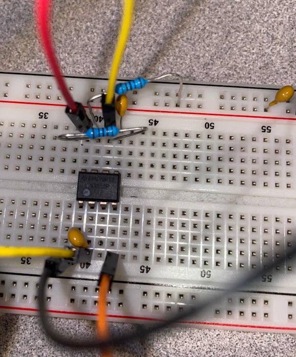
After the build was done, I soldered a 2.2kΩ and a 1kΩ resistor in series to use as a 1/4W dummy load for the NanoVNA. I didn’t bother doing anything fancy with the “dummy load”. I simply let it rest between the antenna terminal and the ground on the connector:

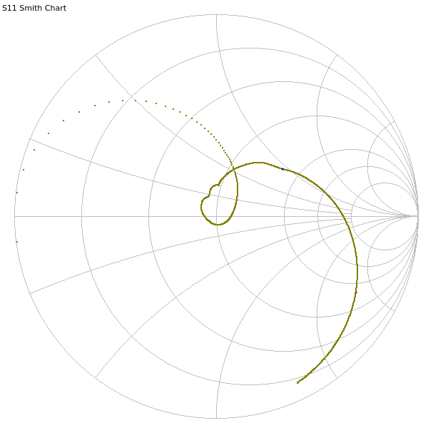
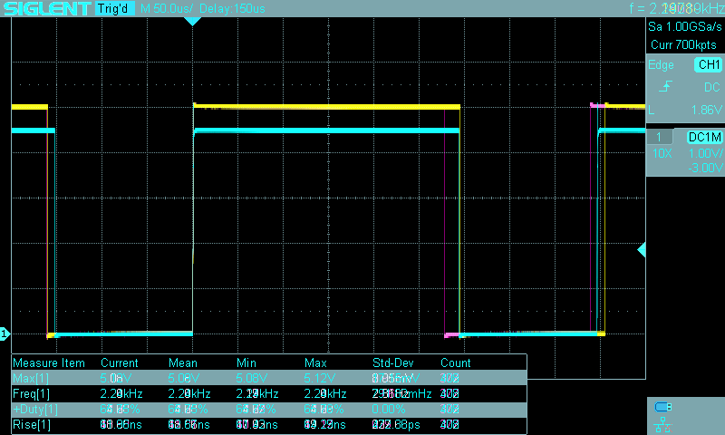
Anyway, here’s the VNA sweep from 1 MHz to 30 MHz:

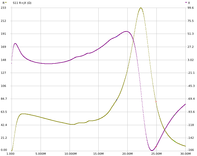
Here is the complex impedance in rectangular coordinates:

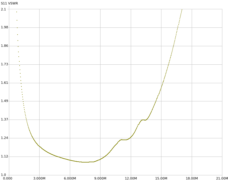
Finally, the SWR is at its lowest (1.085:1) at 7.55 MHz. (Note the different x-axis range.)

Not perfect, but certainly quite usable. And for those that prefer, here’s a table with various amateur radio HF bands:

Band Freq (MHz) SWR Z (Ω) Usable?
160m 1.9 1.321:1 60.4+j11.3 yes
80m 3.6 1.159:1 58-j0.03 yes
60m 5.3 1.111:1 54-j3.77 yes
40m 7.1 1.086:1 49.5-j4.08 yes
30m 10.1 1.166:1 43.3+j2.41 yes
20m 14.1 1.428:1 49.2+j17.7 yes
17m 18.1 2.345:1 82.6+j46.1 yes
15m 21.1 3.895:1 187+j35.6 maybe
12m 24.9 8.341:1 80.5-j158 no
10m 28.1 16.110:1 15.7-j99.7 no

Of course, this is with the 3.2kΩ dummy load. The impedances may be completely different with an actual antenna connected.

I mentioned that I went with smaller toroids to make it more portable. The whole unun weighs 161 g (that’s 5.7 funny units, or 0.36 bigger funny units).

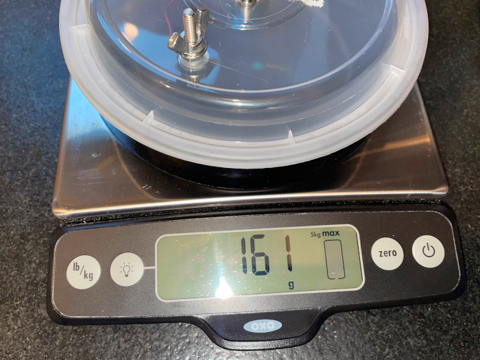
Not super light, but it would have been much worse with 2.4" T240-43 toroids which weigh more than three times as much (106g vs. 33g per toroid).

On-Air Testing

No matter how nice the results of a bench test are, they are irrelevant. What actually matters is on-air performance. So, I packed up my FT-991A, the new unun, and the 40m 1/4 wave antenna’s radiating element (1/4 wave for 40m is the same as 1/2 for 20m) and headed to a nearby park.

I did this two days in a row.

On Saturday (August 13th), I went exclusively with FT4 running 20W. I spent about 1 hour and 12 minutes on-air and got 50 contacts all over Europe, some in North America, and a handful in South America and Africa. A very good activation! (Average: 0.7 contacts/minute)

On Sunday (August 14th), I started with SSB at 66W and later moved to FT4 at 20W. After about an hour and a half and 96 contacts, the SSB pileup kind of dried up, so I switched to FT4 for another hour and a half and another 44 contacts. On SSB, I got only US stations. On FT4, I had a mix of North America and Europe. (Average: 1.04 contacts/minute SSB, 0.5 contacts/min FT4)

Both days, I had the antenna set up as a sloper with the feedpoint (and therefore the unun) about 2 m above ground fed through 100’ of off-brand LMR-240-UF. I know that the repurposed radiating element is too long, but I’ve been too lazy to try to trim it better since the FT-991A’s tuner handles it just fine. The 100’ of coax is completely silly and 20’ would do, but I didn’t have a shorter one handy. The datasheet says that there is 1.60dB loss per 100’ at 30MHz.

With that said, here’s what the NanoVNA showed for the 20m band:

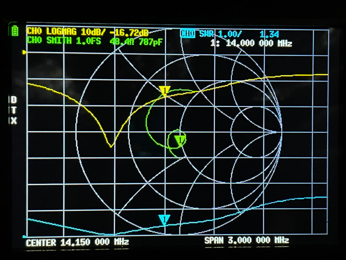
The bottom of the band has SWR of 1.34:1 and the top of the band 1.50:1. The minimum of 1.03:1 is at 13.470 MHz.

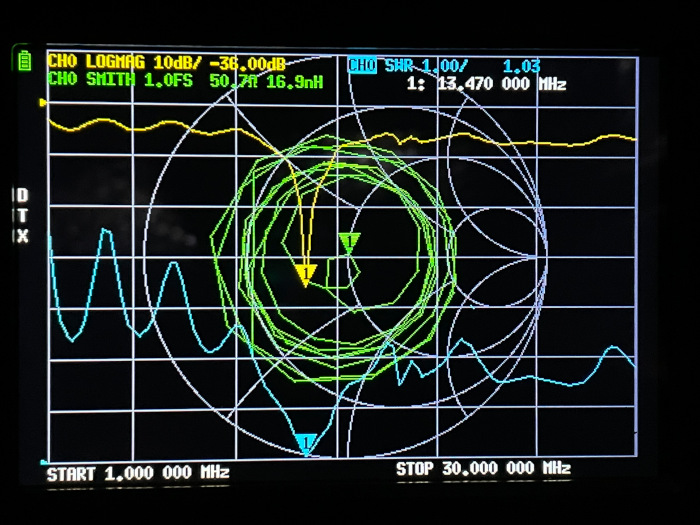
For completeness, here’s the 1–30 MHz sweep:

Future Work

Even though I’ve only used the unun for little over 4 hours, I already started collecting todo items for what to check or build next. For example:

  • Check the unun temperature after transmitting.
  • Possibly move the unun “guts” into a smaller/better box.
  • Try making a 64:1 unun (with 24:3 turns) and compare it to this one.
  • Consider rebuilding it with a larger gauge magnet wire.
  • Cut longer antenna elements and give them a try. Definitely try 80m.

For about $17, I’m very happy with it so far.

555 Timer Comparison

In the late 90s, I messed a little bit with electronics but I stopped because I got interested in programming. This last January, I decided to revisit this hobby.

I went through my collection of random components and found one 555 timer chip—specifically a TS555CN. I played with it on a breadboard and very quickly concluded that I should have more than just one. Disappointingly, sometime over the past 25 years, STM stopped making TS555 in DIP packages, so I ordered NA555PE4s thinking that they should be similar enough.

When they arrived, I tried to make use of them but I quickly noticed that their output seemed…weird. I tweeted about it and then tweeted some more. I concluded that precision 555s just weren’t fundamental enough to most circuits using DIP packages, and that I would have to make do with the NA555 parts.

Fast forward a few months, and I noticed ICM7555IPAZ on Mouser. The datasheet made it look a lot like the TS555…so I bought one to benchmark.

I went with a very simple astable multivibrator configuration—the same one that every 555 datasheet includes:

R1, R2 1kΩ
C1 220nF
C2 0.01μF
C3 10μF

The TS555 datasheet suggested 0.01μF for C2, and it didn’t seem to harm the other two chips so I went with it.

The NA555 datasheet suggested 0.01μF for C3. That cleaned up the rising edge slightly for TS555 and ICM7555. NA555’s rising edge actually became an edge instead of a huge mess, however it still seemed to be limited so I went with a bigger decoupling capacitor—namely 10μF. That didn’t seem to harm the other two chips.

Finally, note that the output is completely unloaded. I figure that this is reasonable since there are plenty of high input impedance loads that the 555 output could feed into. (A quick sanity check with a 1kΩ resitor to ground shows that the output voltage drops by about a volt, but the general shape of the wave doesn’t change.)

I assembled it on a breadboard with plenty of space for my fingers to swap out the chip:

The orange and red wires go to +5V and the black one goes to ground. All 3 are plugged in just right of the decoupling capacitor (off image).

Looking at the three datasheets, they all provide the same (or slightly rearranged) formulas for the frequency and duty cycle. Since I used 1kΩ for the two resistors and 220nF for the capacitor, I should be seeing:

f=1.44(RA+2*RB)*C=2182Hz

and duty cycle:

D=RA+RBRA+2*RB=23 or 66.67%

Because I used a breadboard, there is some amount of stray capacitance which likely shifts the frequency a bit. Based on previous experience, that shouldn’t be too much of an issue.

I supplied the circuit with a power supply set to 5V and 0.2A. (It operated in constant-voltage mode the entire time.)

Unlike some of my previous experiments, I actually tried to get a nice clean measurement this time. I used the probe grounding spring to get a short ground and measured between pin 1 and 3 (ground and output, respectively).

Let’s look at the amplitude, frequency, duty cycle, and rise time of the three chips. I took screenshots of the scope as I was performing the various measurements. To make it easier to compare them, I made combined/overlayed images and tweaked the colors. This makes the UI elements in the screenshot look terrible, but it is trivial to see how the chips compare at a glance. In the combined images TS555 is always yellow, NA555 is cyan, and ICM7555 is magenta.

Amplitude, frequency, and duty cycle

(Individual screenshots: NA555, TS555, ICM7555)

It is easy to see that the output of both TS555 and ICM7555 goes to (and stays at) 5V. The NA555 spikes to 5V during the transition, but then decays to 4.5V. More on this later.

Similarly, it is easy to see that the TS555 and NA555 have a very similar positive cycle time but different enough negative cycle time that their frequencies and duty cycle will be different.

TS555 got close with the frequency (2.20 kHz) while NA555 got close with the duty cycle (65.75%). ICM7555 was the worst of the bunch with 2.28 kHz and 63.23% duty cycle.

Rise time

(Individual screenshots: NA555, TS555, ICM7555)

The NA555 has a comparatively awful rise time of 74.88 ns. The TS555 appears to be a speed demon clocking in at 18.69 ns. Finally, the ICM7555 appears to split the difference with 41.91 ns.

I still think that it is amazing that a relatively inexpensive scope (like the Siglent SDS 1104X-E used for these measurements) can visualize signal changes on nanosecond scales.

Revisiting amplitude

In a way, looking at the amplitude is what got me into this evaluation—specifically, the strange output voltage on the NA555 chip. Let’s take a look at the first microsecond following a positive edge.

(Individual screenshots: NA555, TS555, ICM7555)

After the somewhat leisurely rise time of ~75 ns, the output stays near 5V for about 200 ns, before dipping down to about 3.75V for almost 200 ns and then recovering to about 4.5V over the next 400 ns. The output stays at 4.5V until the negative edge.

This is weird and I don’t have any answers for why this happens. I tried a handful of the NA555s (all likely from the same batch), and they all exhibit this behavior.

NA555 decoupling

As I mentioned in the introduction, I didn’t follow the NA555’s decoupling capacitor suggestion. I wasn’t planning on writing this section, but I think that it is interesting to see just how much the output changes as the decoupling capacitor is varied.

As before, I made combined/overlayed images for easier comparison. This time, yellow is no decoupling capacitor, magenta is 0.01μF (suggested by the NA555 datasheet), cyan is 0.1μF, and green is 10μF (used in chip comparison circuit).

(Individual screenshots: no cap, 0.01μF, 0.1μF, 10μF)

As you can see, not having a decoupling capacitor makes the output voltage go to nearly 7V in a circuit with a 5V supply. Adding the suggested 0.01μ certainly makes things better (the peak is at about 5.8V) but it looks like the chip is still struggling to deal with the transient. Using 0.1μF or more results in approximately the same waveform with a peak just around 5V.

The suggested 0.01μF has another problem in my circuit. It makes the NA555’s output ring:

(Individual screenshots: no cap, 0.01μF, 0.1μF, 10μF)

Neither the TS555 nor the ICM7555 have this issue. They are both quite happy with a 0.01μF capacitor. Without any capacitor, they have a little bit of a ring around 5V (1.2Vpp for TS555, 200mVpp for ICM7555) but it subsides promptly. The ICM7555’s ringing is so minor, that it probably isn’t worth it to even use a decoupling capacitor.

Summary

I’ve collected the various measurements from the screenshots and put them into the following table:

Calculated TS555CN NA555PE4 ICM7555IPAZ
f (kHz) 2.182 2.20 (+0.8%) 2.24 (+2.7%) 2.28 (+4.4%)
D (%) 66.67 64.68 (-3.0%) 65.75 (-1.4%) 63.23 (-5.2%)
Rise (ns) 18.69 74.88 41.91
Logic high peak (V) 5 5.08 5.12 5.08
Logic high steady state (V) 5 5.08 ~4.5 5.08

So, what does this all mean? Ultimately, not a whole lot. The 555 is a versatile chip, but not a magical one. Despite what the NA555 datasheet says, the 555 is not a precision device by modern standards, but it is still an easy way to get a square(-ish) wave around the desired frequency.

With that said, not all 555s are created equal.

The NA555 with all its flaws still works well enough and has a low price. So, for any sort of “crude” timing, it should work well. If, however, the circuit making use of the timer output requires a cleaner signal, then I’d reach for something better.

The ICM7555 is very good. It produces a nice clean output with reasonably fast edges, but not as fast as the TS555. Unfortunately, the performance costs extra—an ICM7555 is about twice the cost of a NA555.

All things being equal, the TS555 and ICM7555 are on par. One has a faster edge, the other has less ringing (and is still actively manufactured). I’ll save the TS555 for future benchmarks. Depending on the application, I’ll either use a NA555 or ICM7555.

Powered by blahgd