Hardware
For this PPS experiment I decided to avoid all control loop/feedback complexity and just manually set the frequency to something close enough and let it drift—hence the unsynchronized. As a result, the circuit was quite simple:
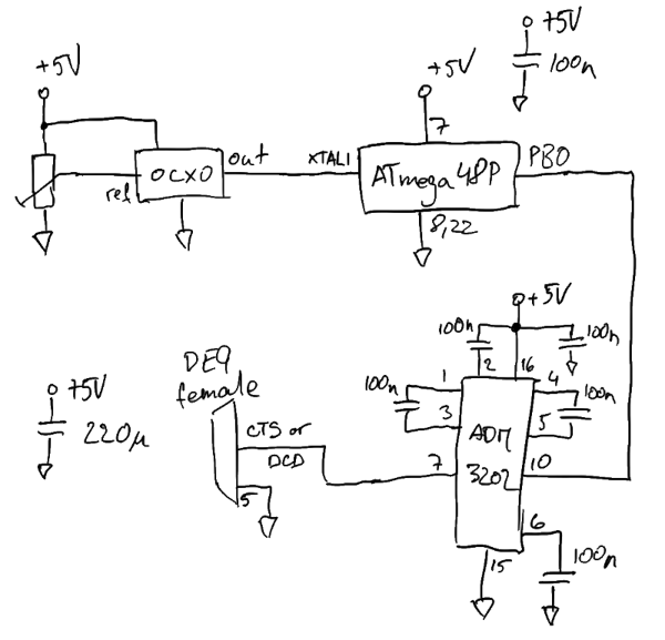
The OCXO was a $5 used part from eBay. It outputs a 10 MHz square wave and has a control voltage pin that lets you tweak the frequency a little bit. By playing with it, I determined that a 10mV control voltage change yielded about 0.1 Hz frequency change. The trimmer sets this reference voltage. To “calibrate” it, I connected it to a frequency counter and tweaked the trimmer until a frequency counter read exactly 10 MHz.
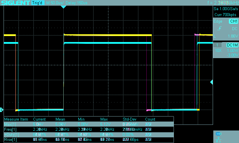
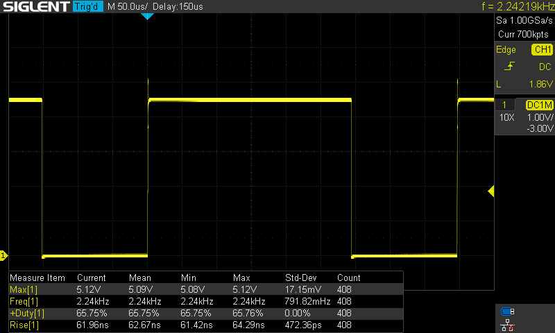
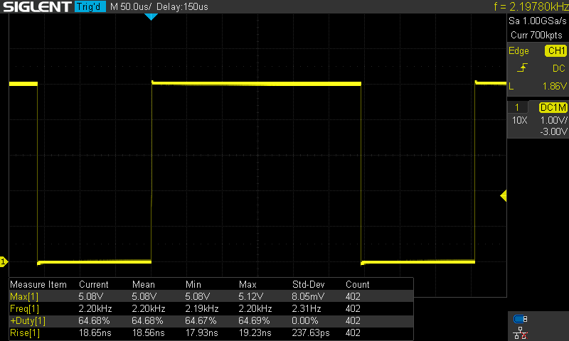
10 MHz is obviously way too fast for a PPS signal. The simplest way to turn it into a PPS signal is to use an 8-bit microcontroller. The ATmega48P’s design seems to have very deterministic timing (in other words it adds a negligible amount of jitter), so I used it at 10 MHz (fed directly from the OCXO) with a very simple assembly program to toggle an output pin on and off. The program kept an output pin high for exactly 2 million cycles, and low for 8 million cycles thereby creating a 20% duty cycle square wave at 1 Hz…perfect to use as a PPS. Since the jitter added by the microcontroller is measured in picoseconds it didn’t affect the overall performance in any meaningful way.
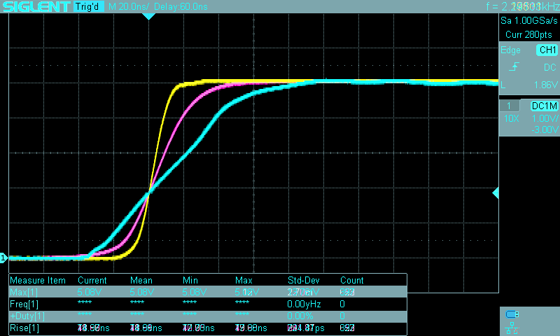
The ATmega48P likes to run at 5V and therefore its PPS output is +5V/0V, which isn’t compatible with a PC serial port. I happened to have an ADM3202 on hand so I used it to convert the 5V signal to an RS-232 compatible signal. I didn’t do as thorough of a check of its jitter characteristics, but I didn’t notice anything bad while testing the circuit before “deploying” it.
Finally, I connected the RS-232 compatible signal to the DCD pin (but CTS would have worked too).
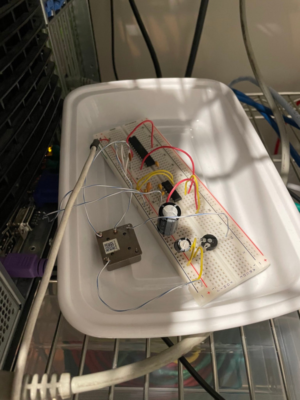
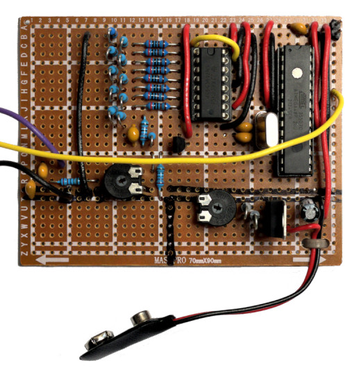
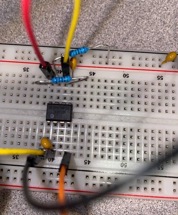
The whole circuit was constructed on a breadboard with the OCXO floating in the air on its wires. Power was supplied with an iPhone 5V USB power supply. Overall, it was a very quick and dirty construction to see how well it would work.
Software
My server runs FreeBSD with chrony as the NTP daemon. The configuration is really simple.
First, setting dev.uart.0.pps_mode to 2 informs the kernel that the PPS signal is on DCD (see uart(4)).
Second, we need to tell chrony that there is a local PPS on the port:
refclock PPS /dev/cuau0 local
The local token is important. It tells chrony that the PPS is not synchronized to UTC. In other words, that the PPS can be used as a 1 Hz frequency source but not as a phase source.
Performance
I ran my server with this PPS refclock for about 50 days with chrony configured to log the time offset of each pulse and to apply filtering to every 16 pulses. (This removes some of the errors related to serial port interrupt handling not being instantaneous.) The following evaluation uses only these filtered samples as well as the logged data about the calculated system time error.
In addition to the PPS, chrony used several NTP servers from the internet (including the surprisingly good time.cloudflare.com) for the date and time-of-day information. This is a somewhat unfortunate situation when it comes to trying to figure out how good of an oscillator the OCXO is, as to make good conclusions about one oscillator one needs a better quality oscillator for the comparison. However, there are still a few things one can look at even when the (likely) best oscillator is the one being tested.
NTP Time Offset
The ultimate goal of a PPS source is to stabilize the system’s clock. Did the PPS source help? I think it is easy to answer that question by looking at the remaining time offset (column 11 in chrony’s tracking.log) over time.
This is a plot of 125 days that include the 50 days when I had the PPS circuit running. You can probably guess which 50 days. (The x-axis is time expressed as  Modified Julian Date, or MJD for short.)
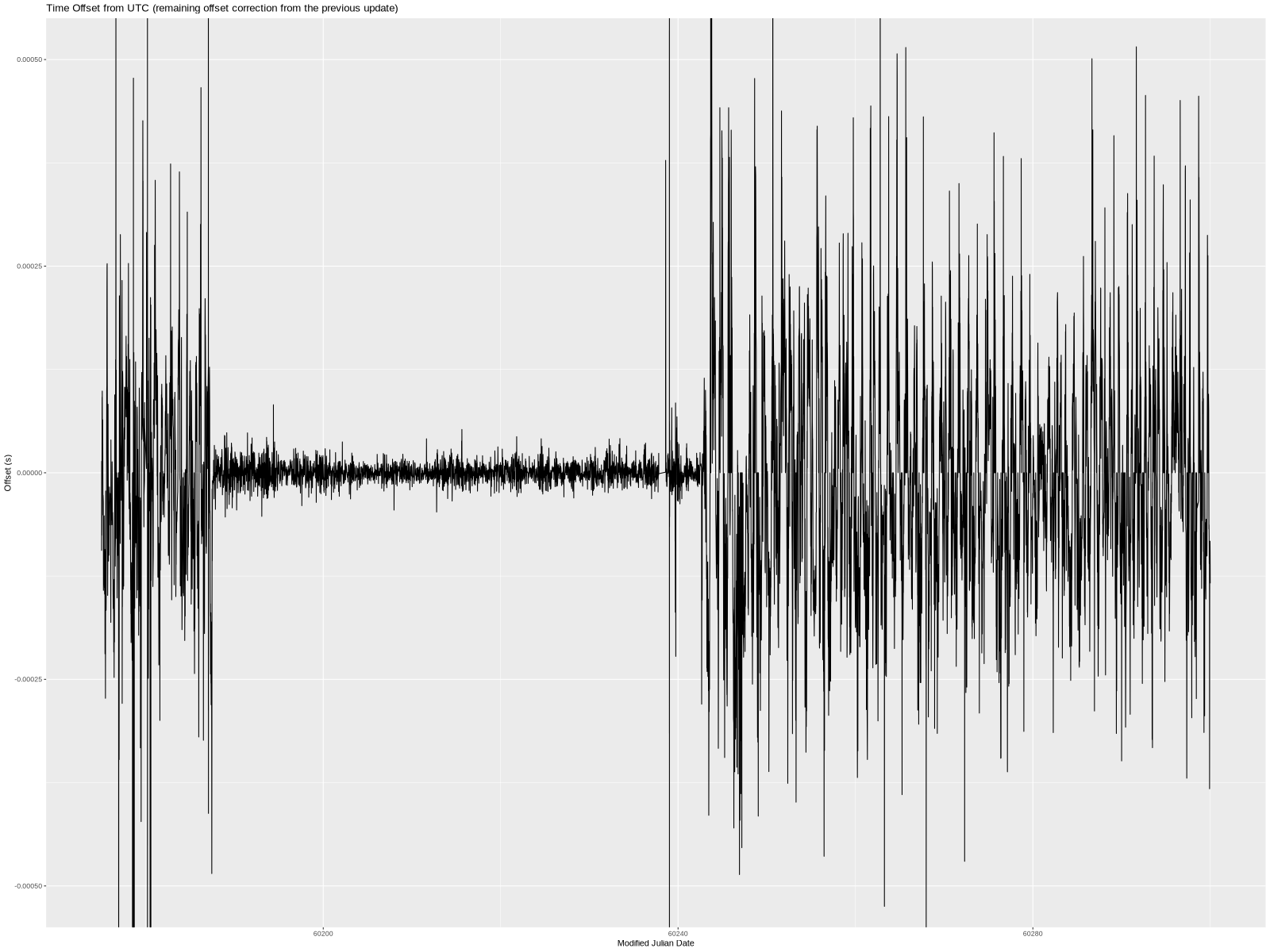
I don’t really have anything to say aside from—wow, what a difference!
For completeness, here’s a plot of the estimated local offset at the epoch (column 7 in tracking.log). My understanding of the difference between the two columns is fuzzy but regardless of which I go by, the improvement was significant.

Fitting a Polynomial Model
In addition to looking at the whole-system performance, I wanted to look at the PPS performance itself.
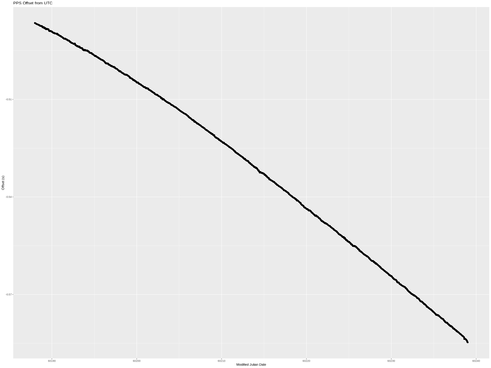
As before, the x-axis is MJD. The y-axis is the PPS offset as measured and logged by chrony—the 16-second filtered values.
The offset started at -486.5168ms. This is an arbitrary offset that simply shows that I started the PPS circuit about half a second off of UTC. Over the approximately 50 days, the offset grew to -584.7671ms.
This means that the OCXO frequency wasn’t exactly 10 MHz (and therefore the 1 PPS wasn’t actually at 1 Hz). Since there is a visible curve to the line, it isn’t a simple fixed frequency error but rather the frequency drifted during the experiment.
How much? I used R’s lm function to fit simple polynomials to the collected data. I tried a few different polynomial degrees, but all of them were fitted the same way:
m <- lm(pps_offset ~ poly(time, poly_degree, raw=TRUE))
a <- as.numeric(m$coefficients[1])
b <- as.numeric(m$coefficients[2])
c <- as.numeric(m$coefficients[3])
d <- as.numeric(m$coefficients[4])
In all cases, these coefficients correspond to the 4 terms in . For lower-degree polynomials, the missing coefficients are 0.
Note: Even though the plots show the x-axis in MJD, the calculations were done in seconds with the first data point at t=0 seconds.
Linear
The simplest model is a linear one. In other words, fitting a straight line through the data set. lm provided the following coefficients:
a=-0.480090626569894
b=-2.25787872135774e-08
That is an offset of -480.09ms and slope of -22.58ns/s (which is also -22.58 ppb frequency error).
Graphically, this is what the line looks like when overlayed on the measured data:
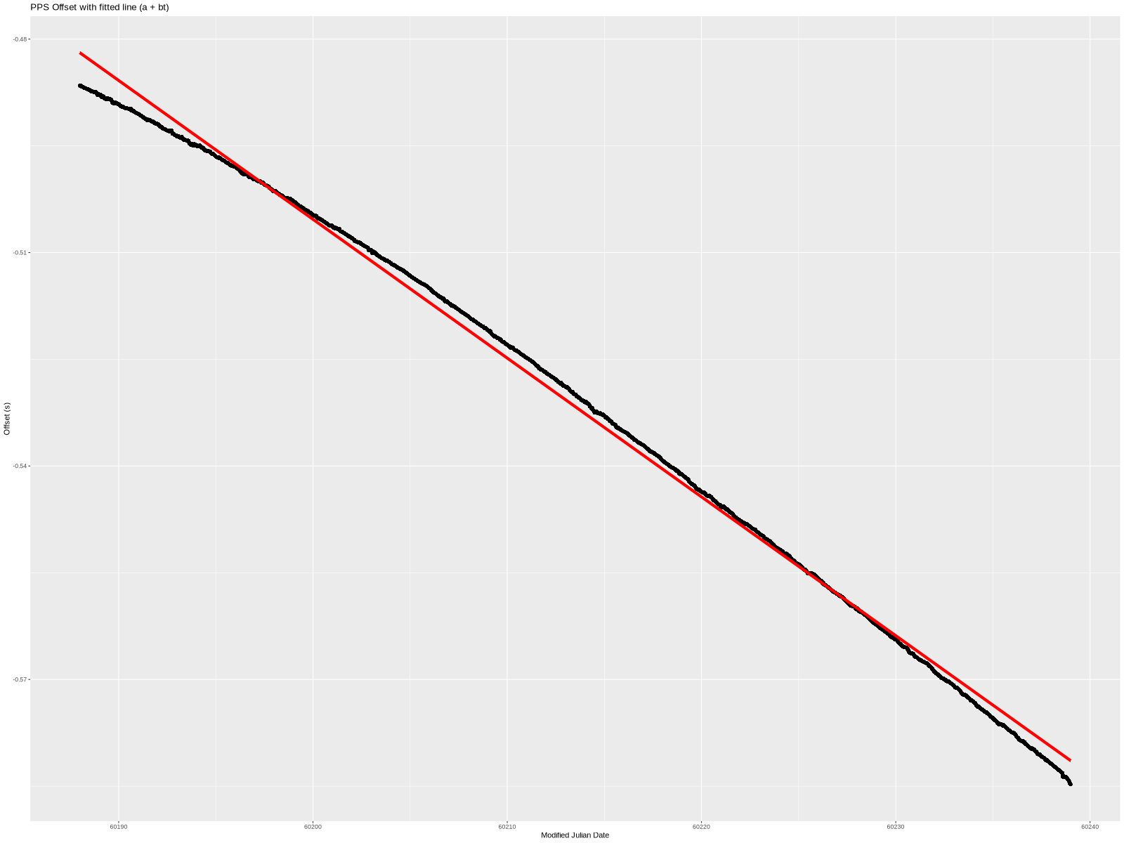
Not bad but also not great. Here is the difference between the two:
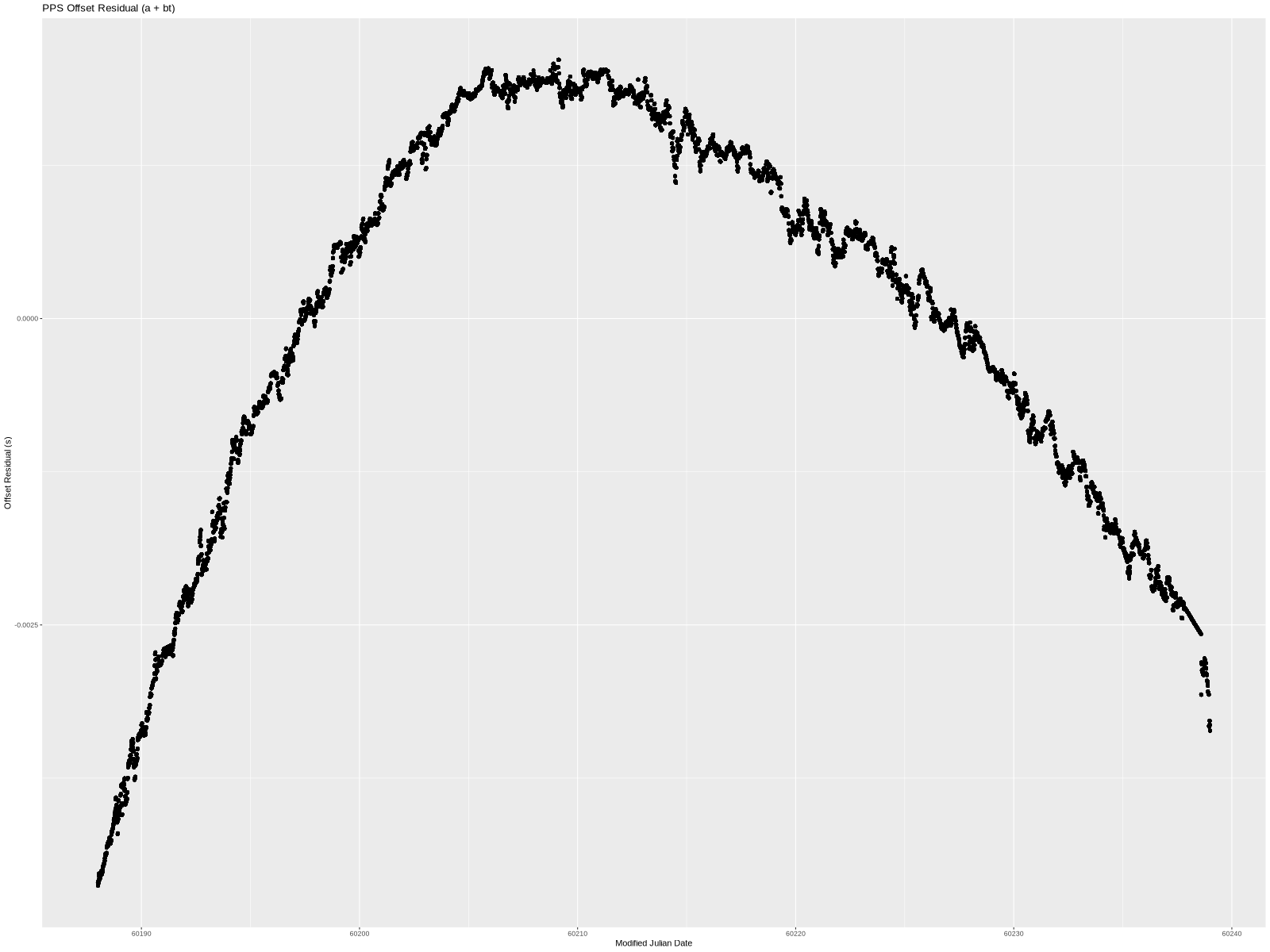
Put another way, this is the PPS offset from UTC if we correct for time offset (a) and a frequency error (b). The linear model clearly doesn’t handle the structure in the data completely. The residual is near low-single-digit milliseconds. We can do better, so let’s try to add another term.
Quadratic
lm produced these coefficients for a degree 2 polynomial:
a=-0.484064700277606
b=-1.75349684277379e-08
c=-1.10412099841665e-15
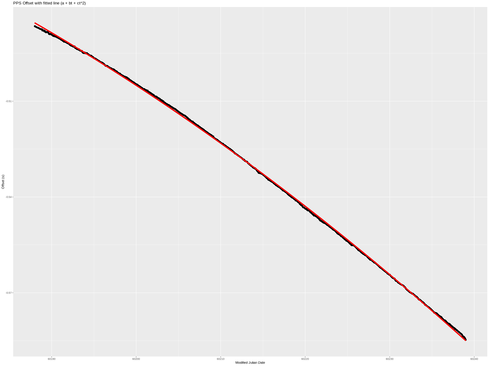
Visually, this fits the data much better. It’s a little wrong on the ends, but overall quite nice. Even the residual (below) is smaller—almost completely confined to less than 1 millisecond.
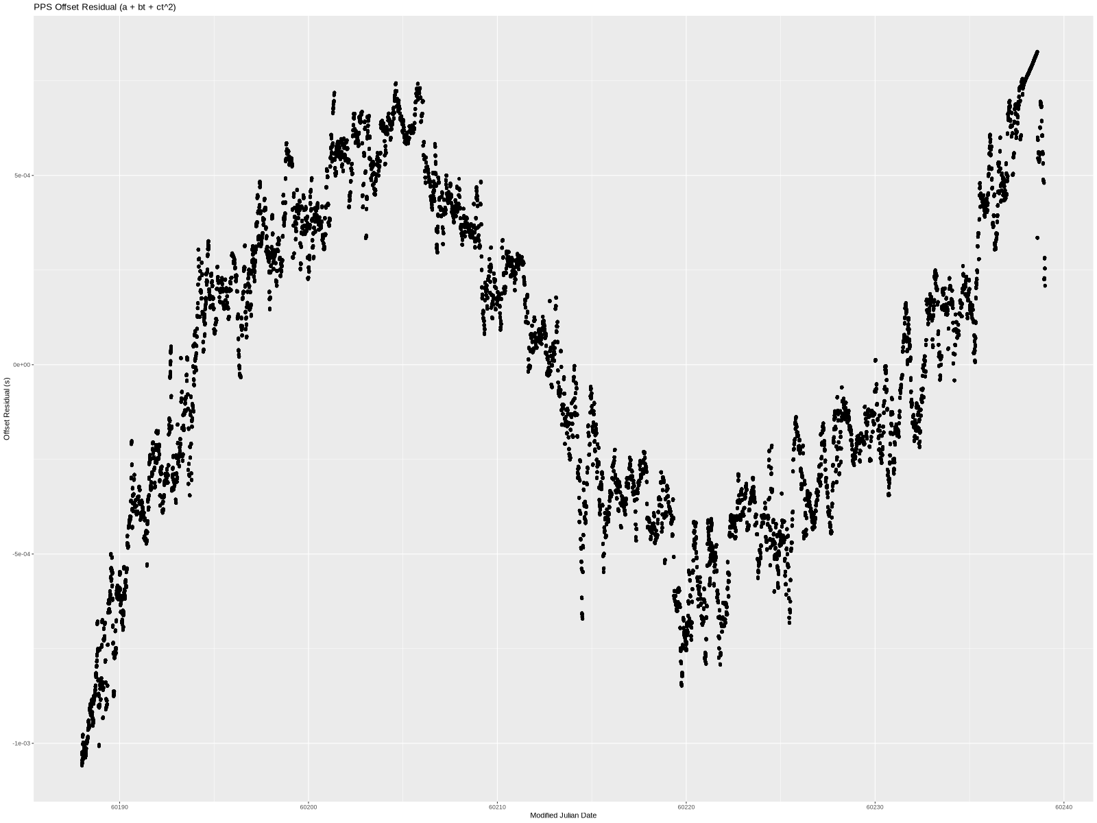
a is still time offset, b is still frequency error, and c is a time “acceleration” of sorts.
There is still very visible structure to the residual, so let’s add yet another term.
Cubic
As before, lm yielded the coefficients. This time they were:
a=-0.485357232306569
b=-1.44068934233748e-08
c=-2.78676248986831e-15
d=2.45563844387287e-22
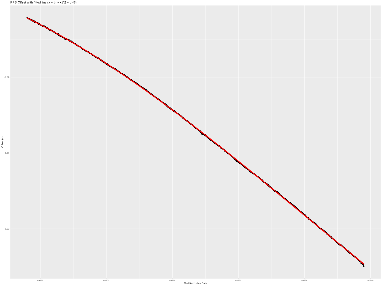
That’s really close looking!
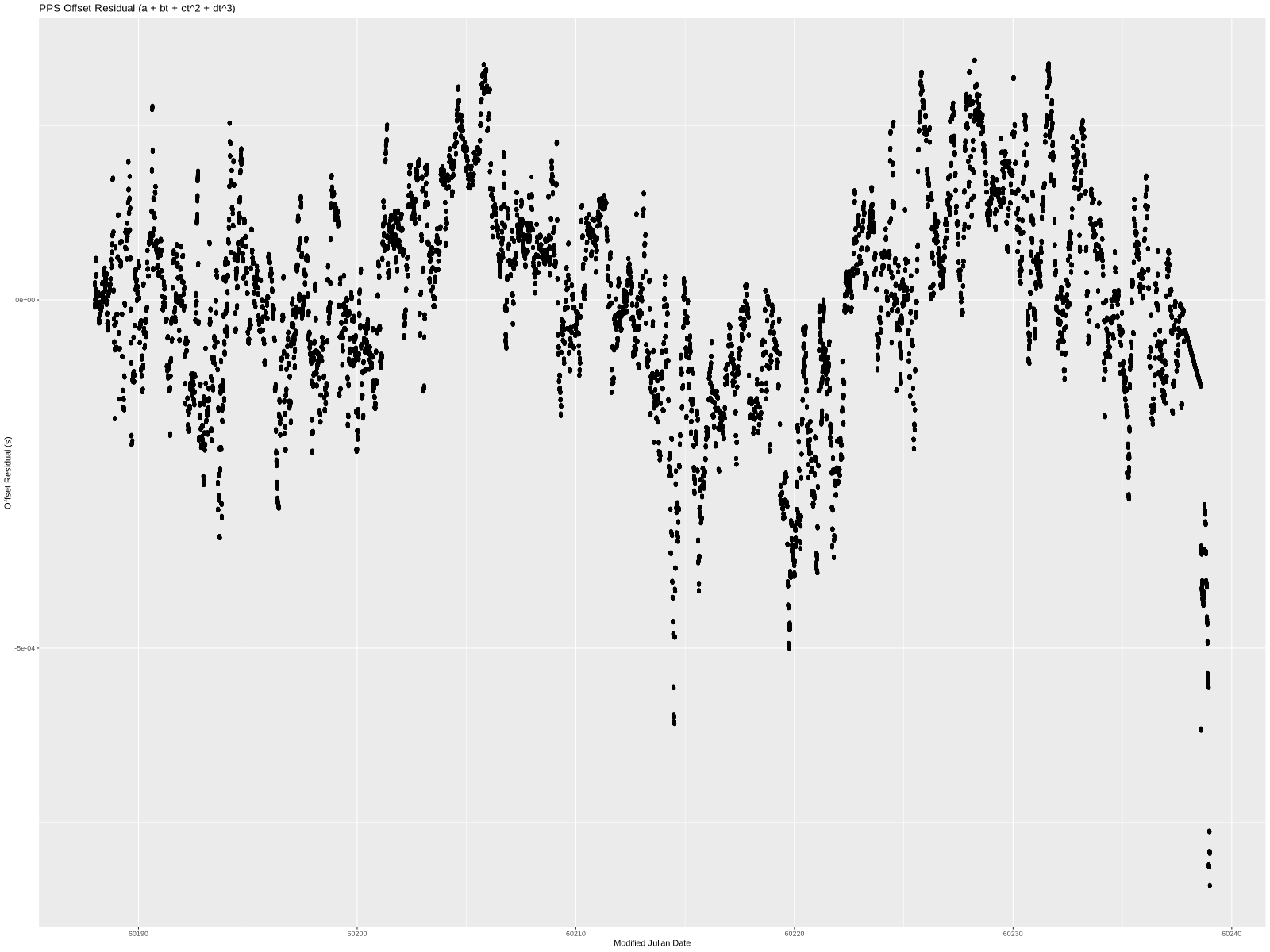
The residual still has a little bit of a wave to it, but almost all the data points are within 500 microseconds. I think that’s sufficiently close given just how much non-deterministic “stuff” (both hardware and software) there is between a serial port and an OS kernel’s interrupt handler on a modern server. (In theory, we could add additional terms forever until we completely eliminated the residual.)
So, we have a model of what happened to the PPS offset over time. Specifically, and the 4 constants. The offset (a of approximately -485ms) is easily explained—I started the PPS at the “wrong” time. The frequency error (b of approximately -14.4 ppb) can be explained as I didn’t tune the oscillator to exactly 10 MHz. (More accurately, I tuned it, unplugged it, moved it to my server, and plugged it back in. The slightly different environment could produce a few ppb error.)
What about the c and d terms? They account for a combination of a lot of things. Temperature is a big one. First of all, it is a home server and so it is subject to air-conditioner cycling on and off at a fairly long interval. This produces sizable swings in temperature, which in turn mess with the frequency. A server in a data center sees much less temperature variation, since the chillers keep the temperature essentially constant (at least compared to homes). Second, the oscillator was behind the server and I expect the temperature to slightly vary based on load.
One could no doubt do more analysis (and maybe at some point I will), but this post is already getting way too long.
Conclusion
One can go nuts trying to play with time and time synchronization. This is my first attempt at timekeeping-related circuitry, so I’m sure there are ways to improve the circuit or the analysis.
I think this experiment was a success. The system clock behavior improved beyond what’s needed for a general purpose server. Getting under 20 ppb error from a simple circuit on a breadboard with absolutely no control loop is great. I am, of course, already tinkering with various ideas that should improve the performance.
]]>Hardware
For this PPS experiment I decided to avoid all control loop/feedback complexity and just manually set the frequency to something close enough and let it drift—hence the unsynchronized. As a result, the circuit was quite simple:
The OCXO was a $5 used part from eBay. It outputs a 10 MHz square wave and has a control voltage pin that lets you tweak the frequency a little bit. By playing with it, I determined that a 10mV control voltage change yielded about 0.1 Hz frequency change. The trimmer sets this reference voltage. To “calibrate” it, I connected it to a frequency counter and tweaked the trimmer until a frequency counter read exactly 10 MHz.
10 MHz is obviously way too fast for a PPS signal. The simplest way to turn it into a PPS signal is to use an 8-bit microcontroller. The ATmega48P’s design seems to have very deterministic timing (in other words it adds a negligible amount of jitter), so I used it at 10 MHz (fed directly from the OCXO) with a very simple assembly program to toggle an output pin on and off. The program kept an output pin high for exactly 2 million cycles, and low for 8 million cycles thereby creating a 20% duty cycle square wave at 1 Hz…perfect to use as a PPS. Since the jitter added by the microcontroller is measured in picoseconds it didn’t affect the overall performance in any meaningful way.
The ATmega48P likes to run at 5V and therefore its PPS output is +5V/0V, which isn’t compatible with a PC serial port. I happened to have an ADM3202 on hand so I used it to convert the 5V signal to an RS-232 compatible signal. I didn’t do as thorough of a check of its jitter characteristics, but I didn’t notice anything bad while testing the circuit before “deploying” it.
Finally, I connected the RS-232 compatible signal to the DCD pin (but CTS would have worked too).
The whole circuit was constructed on a breadboard with the OCXO floating in the air on its wires. Power was supplied with an iPhone 5V USB power supply. Overall, it was a very quick and dirty construction to see how well it would work.
Software
My server runs FreeBSD with chrony as the NTP daemon. The configuration is really simple.
First, setting dev.uart.0.pps_mode to 2 informs the kernel that the PPS signal is on DCD (see uart(4)).
Second, we need to tell chrony that there is a local PPS on the port:
refclock PPS /dev/cuau0 local
The local token is important. It tells chrony that the PPS is not synchronized to UTC. In other words, that the PPS can be used as a 1 Hz frequency source but not as a phase source.
Performance
I ran my server with this PPS refclock for about 50 days with chrony configured to log the time offset of each pulse and to apply filtering to every 16 pulses. (This removes some of the errors related to serial port interrupt handling not being instantaneous.) The following evaluation uses only these filtered samples as well as the logged data about the calculated system time error.
In addition to the PPS, chrony used several NTP servers from the internet (including the surprisingly good time.cloudflare.com) for the date and time-of-day information. This is a somewhat unfortunate situation when it comes to trying to figure out how good of an oscillator the OCXO is, as to make good conclusions about one oscillator one needs a better quality oscillator for the comparison. However, there are still a few things one can look at even when the (likely) best oscillator is the one being tested.
NTP Time Offset
The ultimate goal of a PPS source is to stabilize the system’s clock. Did the PPS source help? I think it is easy to answer that question by looking at the remaining time offset (column 11 in chrony’s tracking.log) over time.
This is a plot of 125 days that include the 50 days when I had the PPS circuit running. You can probably guess which 50 days. (The x-axis is time expressed as Modified Julian Date, or MJD for short.)
I don’t really have anything to say aside from—wow, what a difference!
For completeness, here’s a plot of the estimated local offset at the epoch (column 7 in tracking.log). My understanding of the difference between the two columns is fuzzy but regardless of which I go by, the improvement was significant.
Fitting a Polynomial Model
In addition to looking at the whole-system performance, I wanted to look at the PPS performance itself.
As before, the x-axis is MJD. The y-axis is the PPS offset as measured and logged by chrony—the 16-second filtered values.
The offset started at -486.5168ms. This is an arbitrary offset that simply shows that I started the PPS circuit about half a second off of UTC. Over the approximately 50 days, the offset grew to -584.7671ms.
This means that the OCXO frequency wasn’t exactly 10 MHz (and therefore the 1 PPS wasn’t actually at 1 Hz). Since there is a visible curve to the line, it isn’t a simple fixed frequency error but rather the frequency drifted during the experiment.
How much? I used R’s lm function to fit simple polynomials to the collected data. I tried a few different polynomial degrees, but all of them were fitted the same way:
m <- lm(pps_offset ~ poly(time, poly_degree, raw=TRUE))
a <- as.numeric(m$coefficients[1])
b <- as.numeric(m$coefficients[2])
c <- as.numeric(m$coefficients[3])
d <- as.numeric(m$coefficients[4])
In all cases, these coefficients correspond to the 4 terms in . For lower-degree polynomials, the missing coefficients are 0.
Note: Even though the plots show the x-axis in MJD, the calculations were done in seconds with the first data point at t=0 seconds.
Linear
The simplest model is a linear one. In other words, fitting a straight line through the data set. lm provided the following coefficients:
a=-0.480090626569894
b=-2.25787872135774e-08
That is an offset of -480.09ms and slope of -22.58ns/s (which is also -22.58 ppb frequency error).
Graphically, this is what the line looks like when overlayed on the measured data:
Not bad but also not great. Here is the difference between the two:
Put another way, this is the PPS offset from UTC if we correct for time offset (a) and a frequency error (b). The linear model clearly doesn’t handle the structure in the data completely. The residual is near low-single-digit milliseconds. We can do better, so let’s try to add another term.
Quadratic
lm produced these coefficients for a degree 2 polynomial:
a=-0.484064700277606
b=-1.75349684277379e-08
c=-1.10412099841665e-15
Visually, this fits the data much better. It’s a little wrong on the ends, but overall quite nice. Even the residual (below) is smaller—almost completely confined to less than 1 millisecond.
a is still time offset, b is still frequency error, and c is a time “acceleration” of sorts.
There is still very visible structure to the residual, so let’s add yet another term.
Cubic
As before, lm yielded the coefficients. This time they were:
a=-0.485357232306569
b=-1.44068934233748e-08
c=-2.78676248986831e-15
d=2.45563844387287e-22
That’s really close looking!
The residual still has a little bit of a wave to it, but almost all the data points are within 500 microseconds. I think that’s sufficiently close given just how much non-deterministic “stuff” (both hardware and software) there is between a serial port and an OS kernel’s interrupt handler on a modern server. (In theory, we could add additional terms forever until we completely eliminated the residual.)
So, we have a model of what happened to the PPS offset over time. Specifically, and the 4 constants. The offset (a of approximately -485ms) is easily explained—I started the PPS at the “wrong” time. The frequency error (b of approximately -14.4 ppb) can be explained as I didn’t tune the oscillator to exactly 10 MHz. (More accurately, I tuned it, unplugged it, moved it to my server, and plugged it back in. The slightly different environment could produce a few ppb error.)
What about the c and d terms? They account for a combination of a lot of things. Temperature is a big one. First of all, it is a home server and so it is subject to air-conditioner cycling on and off at a fairly long interval. This produces sizable swings in temperature, which in turn mess with the frequency. A server in a data center sees much less temperature variation, since the chillers keep the temperature essentially constant (at least compared to homes). Second, the oscillator was behind the server and I expect the temperature to slightly vary based on load.
One could no doubt do more analysis (and maybe at some point I will), but this post is already getting way too long.
Conclusion
One can go nuts trying to play with time and time synchronization. This is my first attempt at timekeeping-related circuitry, so I’m sure there are ways to improve the circuit or the analysis.
I think this experiment was a success. The system clock behavior improved beyond what’s needed for a general purpose server. Getting under 20 ppb error from a simple circuit on a breadboard with absolutely no control loop is great. I am, of course, already tinkering with various ideas that should improve the performance.
]]>


